Lake Shore Model 620/622/623/647 Magnet Power Supply User’s Manual
5-8
Error Messages & Troubleshooting
5.5 REAR PANEL CONNECTOR DETAIL
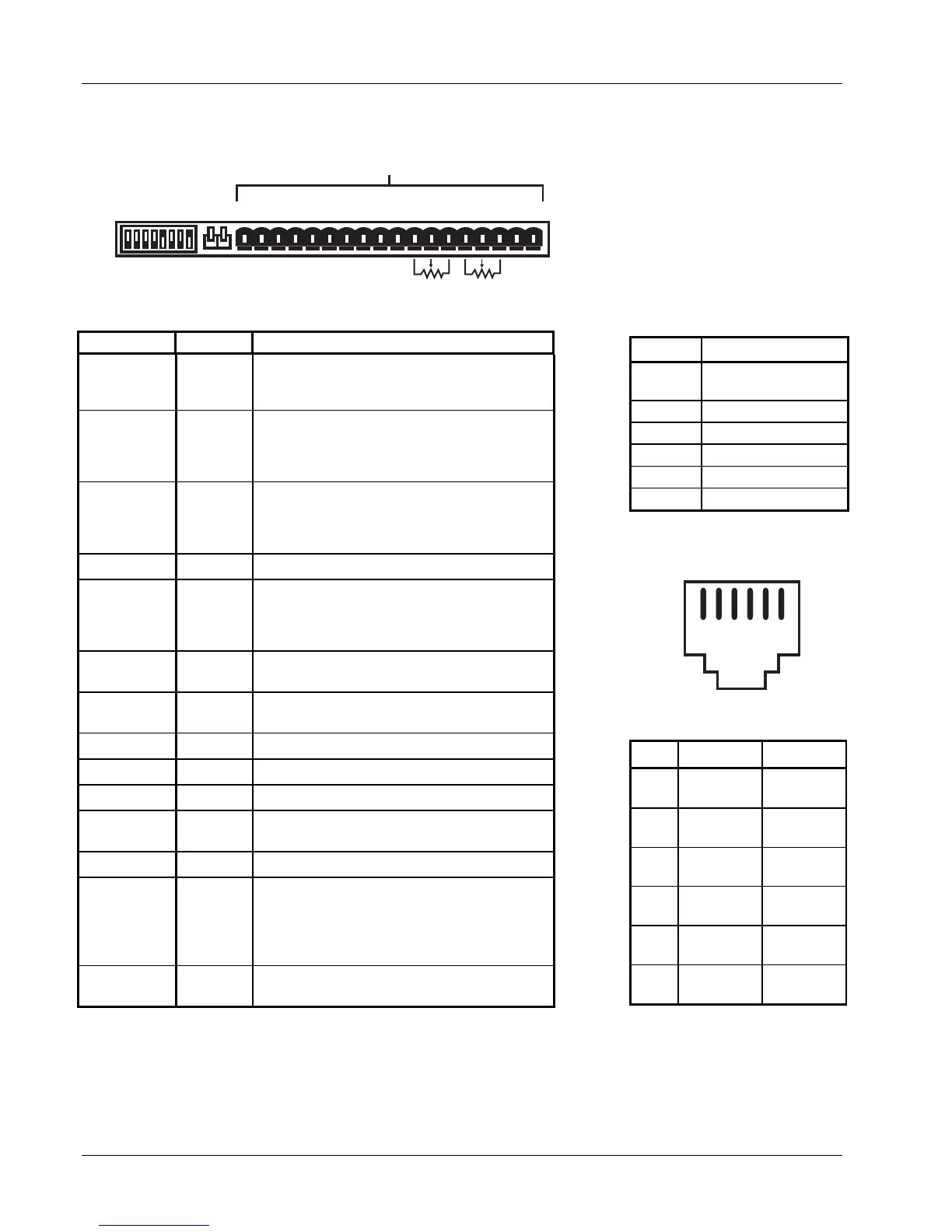
Figure 5-1 MPS Rear Panel Connectors
123456789101112131415161718
+ - + - + - OVP Im Vm m Vp +Vs -ls lp +ls -S +S
CAL AND ID V l
MODE
INT
Vl
EXT
RI FLT ON
10K
MPS Rear Panel Connectors
10K
8 7 6 5 4 3 2 1
Active
Open
Table 5-1B Rear Panel
AL
AND ID Switch Definitions
Switch Function
1 - 3
LSB Multi-
Mainframe Address
4 Multi-Mainframe
5 Dither
6 Not Used
7 Inhibit Delay
8 Calibration
Table 5-1A Rear Panel
onnector De
initions
TERMINAL LABEL DEFINITION
1
2
RI+
RI–
Remote Inhibit – Active low, TTL-compatible
input to remotely disable the output (force the
output settings to 0 A and 1 V).
3
4
FLT +
FLT–
Fault Indicator – Normally open contact closure
to indicate a fault condition has occurred.
Contact rating: 0.25 A resistive at 100 VDC, 3 W,
25 VA.
5
6
ON+
ON–
ON Indicator – Contact closure to indicate when
the front panel circuit breaker is in the ON
position. Contact rating: 0.25 A resistive at 100
VDC, 3 W, 25 VA.
7 Reserved
None
8
OVP
Overvoltage Protection Enable – Analog signal
connected in parallel to other MPS Units to
remotely activate the output overvoltage
protection circuit.
9 Im
Output Current Monitor – Voltage output from Im
to GND(M) is ±0.01 V/A.
10 Vm
Output voltage monitor – Voltage output from Vm
to GND(M) is ±0.01 V/V.
11 m
Monitor and program ground. GND(M).
12 Vp
Factory Use Only
13 +Vs
Factory Use Only
14 –Is
Enable external output current programming via
MODE switch.
15 Ip
Voltage input from Ip to GND(M) is ±0.01 V/A.
16
+Is
A 10 kΩ potentiometer from +Is to –Is with center
tap to Ip produces the minimum voltage for full
scale current output (±1.25 V for Model 622 or
±1.55 V for Model 623). Voltage applied to Ip
sums with internal current programming voltage.
17
18
–S
+S
Remote voltage sense correction. Correction for
load lead drops of up to 0.5 V per lead.
Figure 5-2 Serial
Interface Connector
123456
Table 5-2 Serial Interface
Connector Definition
PIN
RS-232C
FUNCTION
RS-485
FUNCTION
1
No
Function
No
Connection
2
Receive
Data
A
3
Signal
Ground
No
Connection
4
Signal
Ground
No
Connection
5
Transmit
Data
B
6
No
Connection
No
Connection