11
Operations
Operation Instructions
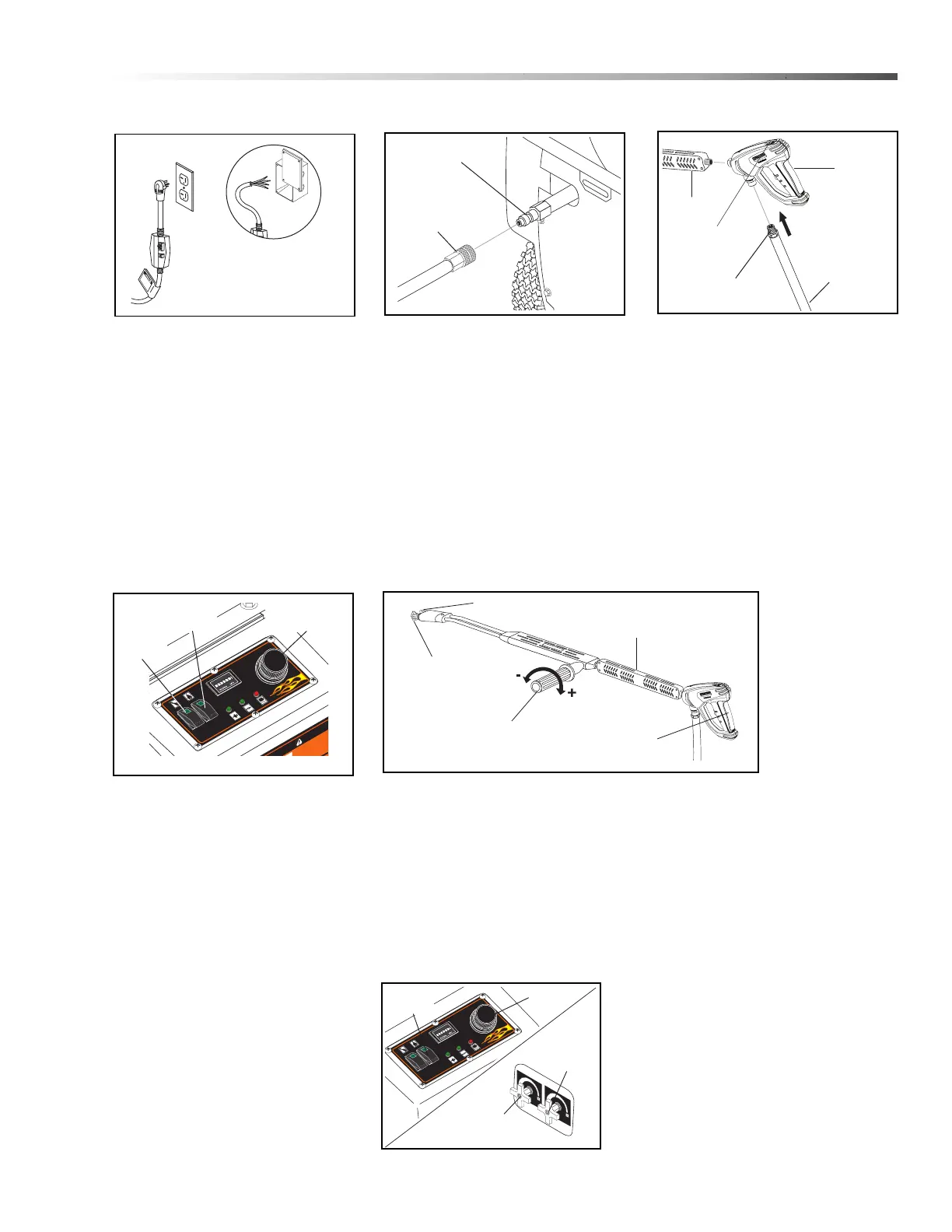
STEP 1: Machines must be
stored indoors when not in use.
Location of machine is important.
Avoid installing near combustible
material or in poorly ventilated
areas. Electrical connection to
machine should be the proper
voltage, phase and amperage. See
specifications for particular model.
Plug the power cord into a
grounded receptacle.
STEP 4: Press the pump switch
"ON" and then pull the trigger on
the spray gun to activate pressure
switch which starts machine (For
auto start machines only).
For machines with time delay shut
down, simply press pump switch
"ON" and the machine will start.
Before installing nozzle, turn on
water supply and run machine
allowing water to flush through the
system until clear.
STEP 2: Connect the high pressure
hose quick coupler to discharge
nipple by sliding the quick coupler
collar back and inserting quick
coupler on to discharge nipple and
pushing the quick coupler collar
forward to secure it.
STEP 3: Attach wand to spray gun
using teflon tape on threads to
prevent leakage. Attach swivel
connector on high pressure hose to
spray gun using teflon tape on
threads. Engage safety latch to
prevent from triggering gun.
Landa PHW Operator’s Manual 8.917-417.0 - D
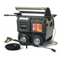
Discharge
Nipple
High Pressure
Hose Quick
Coupler
High
Pressure
Hose
Spray
Gun
Safety
Latch
Wand
Swivel
Connection
RI
S
K
O
F
E
X
P
L
O
SI
O
N.
O
p
er
a
t
e
o
n
l
y
r
e
o
p
e
n
fl
a
m
e
i
s
p
er
m
i
t
-
r
a
y
.
NING
R
T
I
SS
E
ME
N
T
R
IE
S
G
O
DE
E
X
P
L
OS
I
ON
—
U
s
e
e
l
p
r
o
d
u
cto
e
n á
r
e
a
s
d
o
n
d
e
e
l
f
ue
g
o
lla
m
a
se
a
n
p
e
r
m
it
i
d
o
s
.
N
o
roc
i
e
li
q
ui
do
s
infl
ama
b
l
e
s
.
R
I
E
S
G
O
D
E
F
UE
G
O
.
N
o
a
ñ
a
d
i
r
g
a
s
o
l
cua
ndo
l
a
m
ág
u
i
n
a
e
st
e
t
raba
j
a
n
d
o.
R
I
S
Q
UE
D
’
EX
P
L
OS
I
O
N
—
U
t
i
lis
e
r
x
e
n
d
ro
i
t
s
o
ù
u
ne
fl
a
m
m
e
n
u
e
e
s
t
e
.
N
e
p
a
s
va
p
o
r
i
se
r
de
l
iqu
i
d
e
s
.
R
I
SQ
U
E
D
E
F
E
U
.
N
e
e
/d
e
f
u
e
l
ta
nd
i
s
q
ue
l
tion
.
PHW
8
.
91
7
-5
86
.0
PUM
P
B
U
RN
ER
P
OWE
R
IG
N
I
T
I
ON
O
V
ER
LOA
D
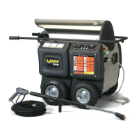
Adjustable
Thermostat
Pump
Switch
Burner
Switch
Variable Pressure
Control Handle
Trigger
Variable Pressure
Wand (VP)
High
Pressure
Nozzle
Brass Soap
Nozzle
STEP 5: Selection of high or low pressure is accompa-
nied by turning the handle. Note: High pressure nozzle
must be inserted at end of wand to obtain high
pressure. To apply soap, see Detergent and General
Cleaning Techniques section.
When a steady stream of water flows from the spray
gun and wand, turn the thermostat knob to the 200°
mark, then push the burner switch. The burner will light
automatically when the spray gun trigger is pulled.
PHW
8.
91
7
-58
6
.
0
PUM
P
B
UR
N
ER
P
O
WE
R
I
G
NI
T
ION O
VERLOAD
DETERGEN
T V
AL
VE
VAL
VUL
A D
E
D
E
TERE
N
T
E
SOUPAPE
D
E D
E
T
E
R
GE
N
T
STEAM
V
A
L
V
E
VAL
VU
LA
D
E
VA
PO
R
S
O
UP
A
P
E
D
E
V
AP
E
UR
Steam
Valve
Detergent
Valve
Burner
Switch
Thermostat
STEP 6: STEAM COMBINATION
OPTION: Turn the steam valve counter-
clockwise.
(Detergent will not siphon when the steam
valve is opened.)
Turn burner switch off, pull trigger on
spray gun and allow water to cool.
 Loading...