Do you have a question about the Landis & Gyr E350 Series 2 and is the answer not in the manual?
| Type | Electricity Meter |
|---|---|
| Current | 5 A |
| Frequency | 50 Hz |
| Display | LCD |
| Operating Temperature | -25°C to +55°C |
| Protection Class | IP54 |
| Accuracy Class | Class 1 or Class 2 |
| Voltage | 230 V |
| Communication | Optical |
| Storage Temperature | -40 °C ... +70 °C |
Specifies the meter versions covered by this manual for different network types and configurations.
Outlines the manual's scope, covering meter characteristics, safety, and service life procedures.
Identifies the intended audience as technically qualified personnel from energy supply companies.
Lists related technical data and functional description documents for ZCF100 meters.
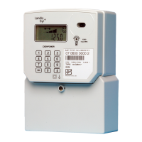
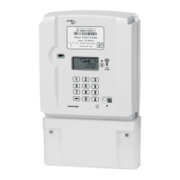
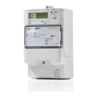
Provides an overview of the meter's physical appearance and key external components.
Details the meter's application in 1-phase networks and its data communication capabilities.
Describes the basic series, disconnector function, extensions, and parameterisation options.
Lists the key features and capabilities of the E350 meters, including measurement accuracy and interfaces.
Explains the alphanumeric code used to identify meter variations, features, and versions.
Details the internal workings, including inputs, outputs, power supply, memory, and signal generation.
Lists the real-time measured values such as voltage, current, frequency, and power factor.
Outlines the optional security features designed to detect unauthorized access or manipulation.
Describes the function and control of the optional disconnector for load limitation or disconnection.
Introduces Landis+Gyr's MAP110 service tool for meter testing, installation, and servicing.
Explains the warning symbols (Warning, Caution, Note) used to convey danger levels and information.
Defines the owner's responsibility for ensuring personnel competence and adherence to safety instructions.
Provides critical instructions for installation, handling, and cleaning to prevent injury and damage.
Discusses potential radio interference issues, especially when combined with certain communication modules.
Describes the external structure and components of the meter, excluding internal construction.
Details the information presented on the meter's front faceplate, including meter data and symbols.
Illustrates typical wiring configurations for different meter models, referencing faceplate information.
Provides detailed physical measurements and diagrams of the meter and its terminal cover.
Step-by-step guide for correctly mounting the meter onto a board or surface.
Instructions for safely and correctly connecting the phase and neutral wires, including overcurrent protection.
Verification steps to ensure correct meter installation, wiring, and sealing before operation.
Procedures for putting the meter into service and verifying its basic functions and display.
Detailed steps for safely removing the meter from the network, emphasizing fuse removal and wire disconnection.
Describes the function of the physical controls on the meter, like the display and disconnector buttons.
Details the meter's display layout, elements, OBIS codes, sequences, errors, and status messages.
Explains the purpose and function of the red test diode for meter testing and pulse output.
Covers the meter's optical port for data readout, software download, and communication.
Explains methods for reading meter data via LCD or optical interface, including protocols and configurations.
Describes the feature for locking the optical port after incorrect password attempts to enhance security.
Guides on initial troubleshooting steps when the LCD or data readout is not functioning.
Explains the types of errors, error code structure, and how persistent errors require service.
Outlines the procedure for meter repair, including removal, error description, packing, and sending to service.
Covers meter testing procedures, frequency, and the need for substitute meters during testing.
Provides instructions for cleaning the meter, emphasizing safety and avoiding water penetration.
Refers to section 4.5 for the procedure of disconnecting and removing the meter from the mains.
Explains how to dispose of meter components responsibly, adhering to environmental regulations.