Do you have a question about the Laney A1 and is the answer not in the manual?
List of essential safety guidelines and warnings for operating the product to prevent hazards.
Details permissible noise exposure limits and recommendations for hearing protection.
Alerts user to dangerous voltage within the enclosure that may cause shock.
Warns against removing the cover and exposing the appliance to rain or moisture.
Ensures correct power supply connection and grounding before plugging in.
Explains wiring conventions and guides initial setup procedures.
A message from the CEO and a brief history of Laney amplifiers.
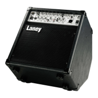
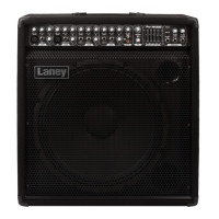
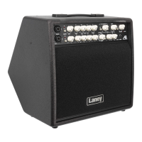
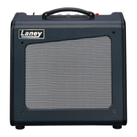
Details the A1's specifications, including power, speaker, and cabinet design.
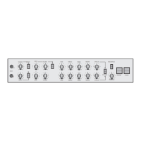
Details instrument input, compressor controls, and the pad switch function.
Covers Enhance, Bass, Mid, Treble, Brilliance EQ, and Phase switch for tone shaping.
Addresses feedback issues and manages volume levels for channel 1 and master output.
Details XLR/1/4" inputs, channel 2 volume, EQ, and mute functions.
Covers channel 3 volume, RCA inputs, and effect assignment to channels 1 & 2.
Allows setting effects level and selecting programs for digital effects.
Details the DI output for external connections and XLR pin assignments.
Details the power inlet socket and the location and importance of the main fuse.
Describes the headphone jack function and the tuner output signal.
Explains the Send and Return sockets for connecting external effects units.
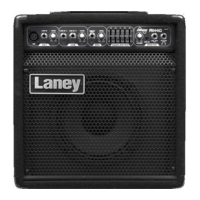
Highlights the versatile kickback design for stage monitor use.
Details safe power procedures and correct cable usage for optimal performance.
Warns about high sound levels and potential hearing damage.
Illustrates a basic connection setup for the amplifier.
Shows a more complex setup with additional equipment connected.
Illustrates the internal signal path and component relationships within the amplifier.
Covers voltage, fuse, power consumption, output power, THD, and loudspeaker.
Lists specific controls, EQ, inputs, and features for Channels 1, 2, and 3.
Covers tuner out, FX loop, cabinet design, size, and weight.