15
Board Layout
Chapter 3
Embedded and Industrial Computing
LAN1/LAN2 Ports (CN13/CN14): The LAN ports are
provided by Intel 82574L Ethernet controller whose
interface complies with PCI-e 1.1 (2.5 Ghz). It has advanced
management features including IPMI pass-through via
SMBus or NC-SI, WOL, PXE remote boot, ISCSI boot and
VLAN filtering.
Pin No. Description
Fast Ethernet Gigabit Ethernet
1 TX+ BI_DA+
2 TX- BI_DA-
3 RX+ BI_DB+
4 -- BI_DC+
5 -- BI_DC-
6 RX- BI_DB-
7 -- BI_DD+
8 -- BI_DD-
Clear CMOS jumper (JP1): It is for clearing the CMOS
memory.
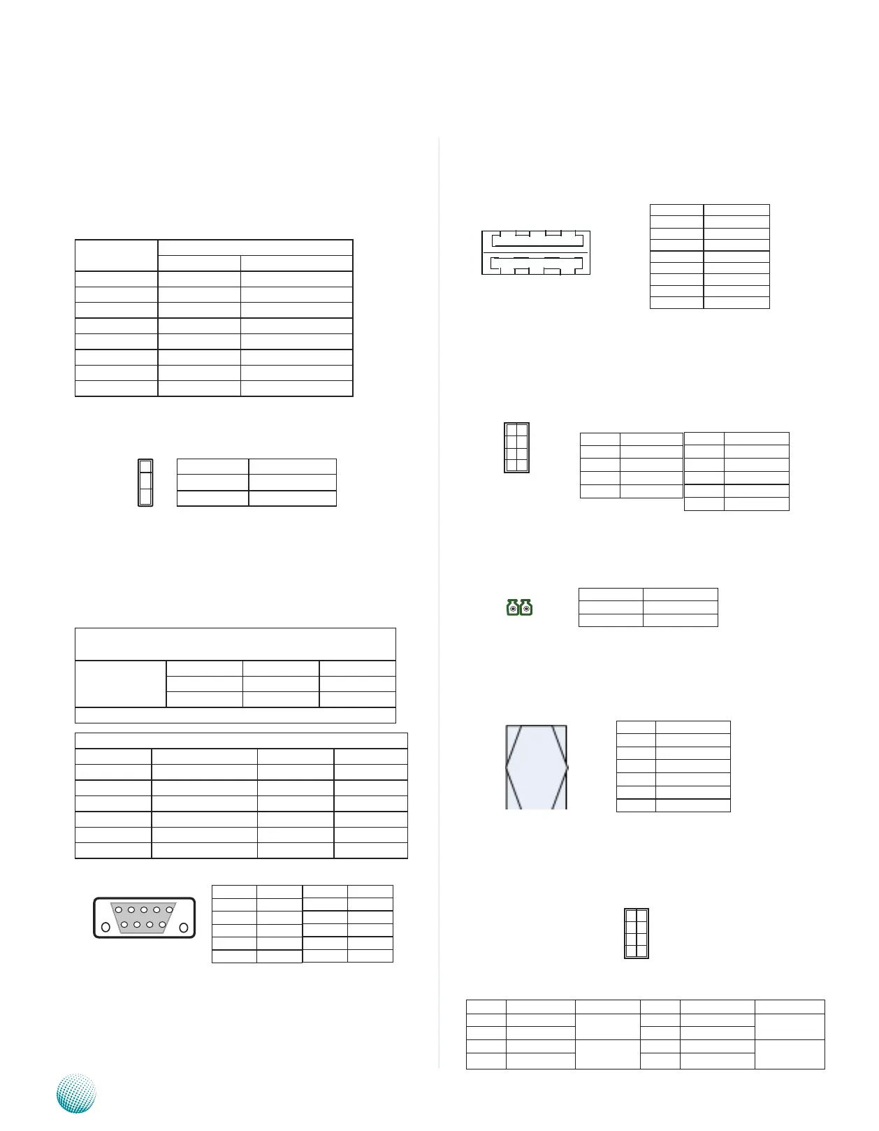
Digital I/O (CN6)
Digital IN/OUT(DIO1) Connector: The 8 pins of General
Purpose Input/Output (GPIO) support input and output
operations through the DB-9 female connector.
TTL Level is +5V; Maximum input/output current for
each port is 50mA
Input/Output Voltage Logic Register
0~2V Low 0
2~5V High 1
The default value is 0
DIO Address
Address Description Address Description
0x2e SUPERIO_INDEX 0x08 GPIO3
0x2f SUPERIO_DATA 0x10 GPIO4
0x07 BANK_REG 0x20 GPIO5
0x01 GPIO0 0x40 GPIO6
0x02 GPIO1 0x80 GPIO7
0x04 GPIO2
Dual USB Port Connector #0 and #1 (USB1):
Dual USB Port Connector #2 and #3 (USB2)
USB 2.0 Pin Header (J11, USB#4 and #5):
External Power Button (J1):
SIM Card Socket (CN8):
Front Panel Function Pin Header (J5, on the backside):
It provides LED signal and button function on the front
panel.
Pin No. Pin Name
1-2 Normal (Default)
2-3 Clear CMOS
1
2
3
Pin No. Pin Name
1 Input0
2 Input1
3 Input2
4 Input3
5 GND
Pin No. Pin Name
6 Output0
7 Output1
8 Output2
9 Output3
9 8 7 6
5 4 3 2 1
Pin No. Pin Name
1 +5V
3 USBD4-
5 USBD4+
7 Ground
Pin No. Pin Name
2 +5V
4 USBD5-
6 USBD5+
8 Ground
10 NC
10
8
6
4
2
9
7
5
3
1
PIN NO. DESCRIPTION
1 PWR_BTN_N
2 GND
1 2
Pin No. Description
C1 UIM_PWR
C2 USIM_RESET
C3 USIM_CLK
C5 GND
C6 USIM_VPP
C7 USIM_DATA
C5 C7
C1 C3
Pin No. Pin Name Function Pin No. Pin Name Function
1 HD_LED+ HDD LED 2 PWR_LED+ Power LED
3 HD_LED- 4 PWR_LED-
5 Reset System Reset
Button
6 POWER_BTN- Power On/Off
Push Button
7 GND 8 GND
1
3
5
7
2
4
6
8
Pin No. Function
1 +5V
2 USBD0-
3 USBD0+
4 GND
5 +5v
6 USBD1-
7 USBD1+
8 GND
1 2 3 4
5 6 7 8