3) How To Power-ON the Testkit
3.1 Connection Diagram
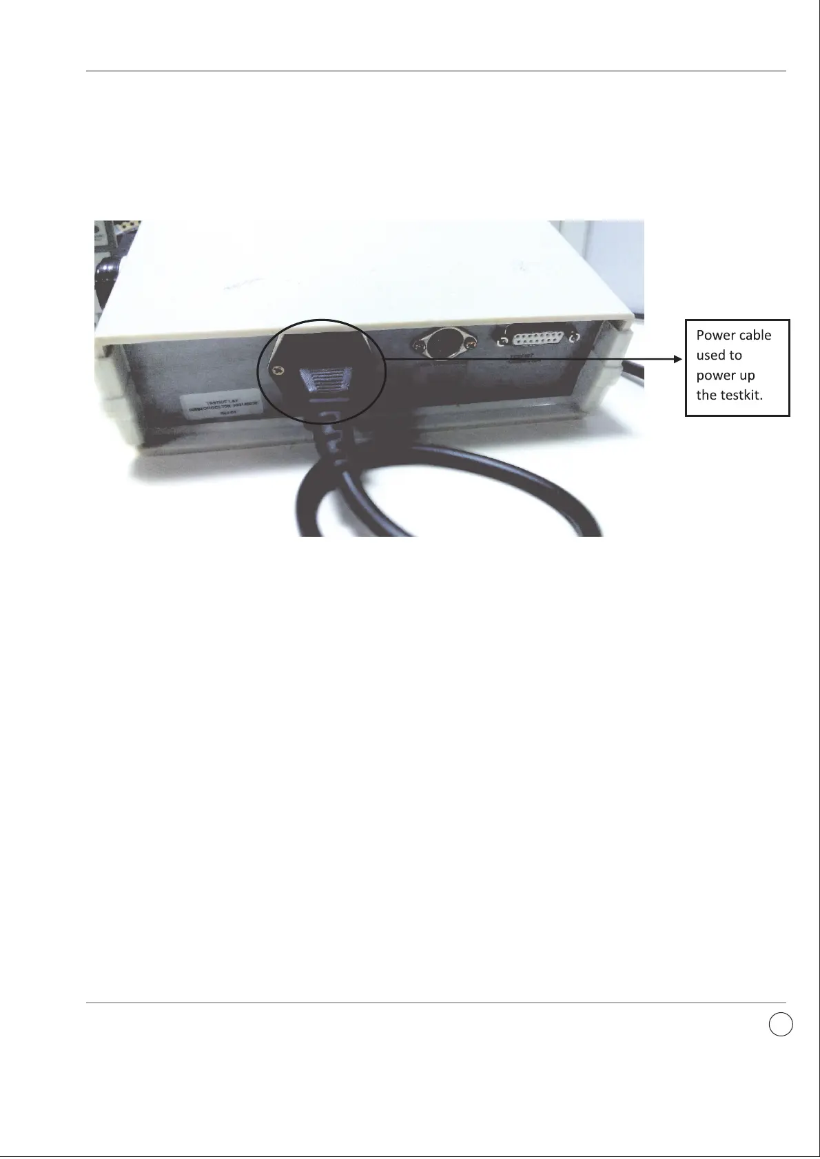
3.1.1 Test kit Rear panel
- It has power cable connector, communication connector
and 15 pin test kit connector.
- Power connector is used to Power-ON the testkit through . power cord ( Part No. Xk13219)
- 15 Pin Test kit connector for connecting cable is used to test the releases.
-. The voltage required to Power-ON the testkit is 240 Vac
6
- Communication connector is used for SR 71 and UN-RS3.
 Loading...