The iCE40 UltraPlus 8:1 Mic Aggregation Demo is a specialized hardware and software solution designed to aggregate audio data from up to eight Pulse Density Modulation (PDM) microphones onto a single data wire using a customized I2S 8-channel aggregation format. This demo addresses the market need for efficiently transferring multi-channel audio data, particularly in applications where standard I2S protocols, typically limited to two channels (LEFT and RIGHT), are insufficient. The core of the demo leverages the iCE40 UltraPlus FPGA, specifically FPGA-B on the primary iCE40 UltraPlus Mobile Development Platform (MDP), in conjunction with a daughter board equipped with eight PDM microphones.
Function Description
The primary function of the iCE40 UltraPlus 8:1 Mic Aggregation Demo is to capture audio from eight PDM microphones, convert these PDM data streams into Pulse Code Modulation (PCM) format, aggregate them into a single I2S 8-channel stream, and then provide options for both monitoring this aggregated stream via an oscilloscope and outputting selected audio channels to headphones.
The functional block diagram illustrates a clear processing pipeline:
- PDM to PCM Conversion: Each of the eight PDM microphones generates a PDM data stream. These streams are fed into a PDM2PCM block within the iCE40 UltraPlus FPGA. This block utilizes an efficient Cascaded Integrator-Comb (CIC) Filter, followed by a Compensation Filter, to accurately convert the PDM data into PCM format for each microphone channel.
- I2S 8-channel Aggregation: The eight individual PCM format streams are then routed to a serializer Time-Division Multiplexing (TDM) block. This TDM block is responsible for serializing the PCM data from all eight channels into a single I2S 8-channel aggregation format. This aggregated data stream, comprising I2S SCK (8-ch), I2S WS (8-ch), and I2S DATA (8-ch) signals, is made available at board header J30 for external monitoring, such as with an oscilloscope.
- Audio Output and Channel Selection: For audio output to headphones, the I2S 8-channel aggregation format is also directed to an I2S Decoder block. This decoder has a crucial role in selecting which audio content is sent to the audio DAC amplifier. Users can choose between two modes:
- Average of all eight PCM channels: In this mode, the decoder processes the combined audio from all eight microphones.
- Individual channel selection: The user can sequentially select one of the eight individual PCM channels to be converted into a standard 2-channel I2S format (I2S SCK (1-ch), I2S WS (1-ch), I2S DATA (1-ch)) and sent to the audio DAC. This selection is controlled by the "MODE" push button on the 8 to 1 Mic Aggregator Board. The audio DAC then drives the sound to a standard 3.5 mm headphone jack.
Important Technical Specifications
- FPGA Device: iCE40 UltraPlus FPGA (specifically FPGA-B on the iCE40 UltraPlus MDP).
- Microphone Type: Eight Pulse Density Modulation (PDM) microphones.
- Audio Output: Standard 3.5 mm audio jack for headphones.
- Aggregation Format: Customized I2S 8-channel aggregation format.
- Channel Selection: User-selectable via a push button on the daughter board, allowing for output of either an average of all eight channels or individual channels.
- Signal Monitoring: Aggregated I2S signals (SCK, WS, DATA) are accessible at header J30 on the MDP board for oscilloscope connection.
- I2S Aggregation Signal Format: The TDM format for eight channels allocates 32 bits per channel. The Word Select (WS) signal indicates the start of each channel's data, with vertical lines marking the first Most Significant Bit (MSB) of each microphone channel.
- Software Requirement: Lattice Radiant Programmer (Version 1.0 or later) for programming the bitstreams.
- Hardware Components:
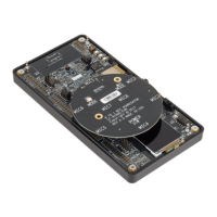
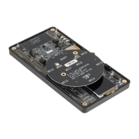
- iCE40 UltraPlus Mobile Development Platform (MDP) (PN: ICE40UP5K-MDP-EVN).
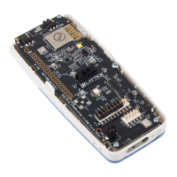
- 8 to 1 Mic Aggregator Board (Daughter Board) (PN: LF-81AGG-EVN).
- Standard 3.5 mm headphones.
Usage Features
- Easy Setup: The demo requires connecting the iCE40 UltraPlus MDP to a PC via USB, powering it on, and then connecting the 8 to 1 Mic Aggregator Board to the MDP. Specific jumper and switch settings on the MDP are required for proper configuration.
- Bitstream Programming: The Lattice Radiant Programmer software is used to load the demo bitstream onto the iCE40 UltraPlus device's external SPI Flash memory. This involves selecting the target memory, port interface, access mode (Direct Programming), operation (Erase, Program, Verify), and specifying the bitstream file.
- Headphone Monitoring: Once the bitstream is loaded, the daughter board's green POWER LED and yellow MODE LED illuminate, indicating the default selection mode (all eight microphones averaged). Sound can be heard through connected headphones.
- Interactive Channel Selection: The "MODE" push button on the 8 to 1 Mic Aggregator Board allows users to cycle through the individual microphone channels (MIC1 through MIC8) and the "ALL MICS" (averaged) mode. The MODE LED on the daughter board is ON when "ALL MICS" mode is selected and also while the MODE button is being pressed during channel sequencing.
- Oscilloscope Signal Observation: Users can connect an oscilloscope to header J30 on the iCE40 UltraPlus MDP to observe the I2S 8-channel aggregation signals (DATA, SCK, WS) and the I2S 2-channel standard signals. This feature is invaluable for debugging and understanding the timing and format of the aggregated audio data. Specific pin assignments for connecting to the oscilloscope are provided, including data, clock, word select, and ground connections for both the 8-channel aggregated and 2-channel standard I2S signals.
Maintenance Features
- Configuration Instructions: The user guide provides detailed instructions for configuring the iCE40 UltraPlus MDP, including specific shunt and switch settings (e.g., SW5-1 ON, SW5-2 OFF, installing a 0-Ω resistor at R30 if not present). These instructions are crucial for ensuring the board is correctly set up for the demo.
- Software Tooling: The reliance on Lattice Radiant Programmer ensures that users can update or re-program the device with new bitstreams or configurations as needed.
- Bill of Materials (BOM): A comprehensive Bill of Materials for the 8 to 1 Mic Aggregator Board is provided, listing all components, their quantities, descriptions, packages, manufacturers, and part numbers. This information is useful for troubleshooting, repair, or understanding the board's construction.
- Schematic Diagram: An appendix includes the schematic diagram of the 8 to 1 Mic Aggregator Card, which is essential for advanced users or engineers who need to understand the circuit design, perform detailed analysis, or diagnose hardware issues.
- Technical Support: Lattice Semiconductor offers technical support for assistance, encouraging users to submit a technical support case via their website.
- Revision History: The user guide includes a revision history, detailing changes and updates made to the document over time. This helps users track modifications, understand the evolution of the demo, and ensure they are working with the most current information. For example, updates include changes to software tool references, device properties images, and additions to functional descriptions.