Fig.2
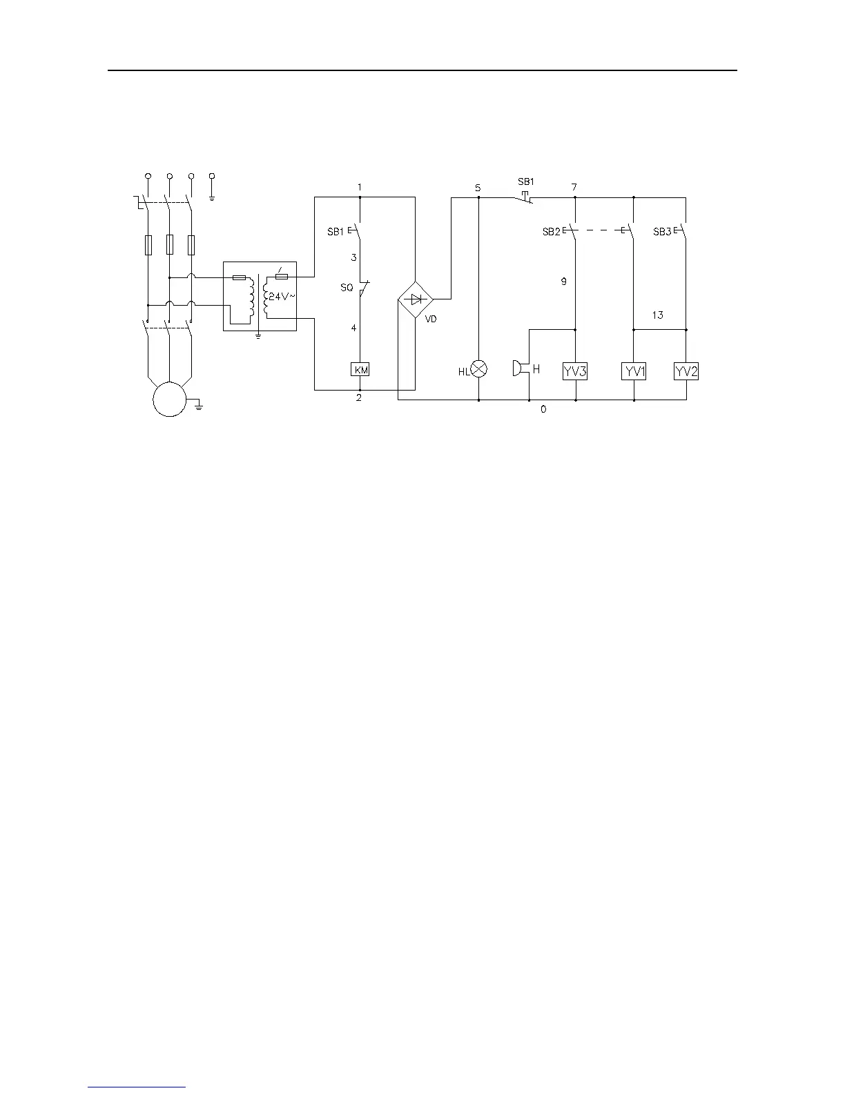
Lifting process: Press UP button SB1, The motor will
drive the pump and send oil to the cylinder, which will in turn
raise the platform upward. Release button SB1, the platform
will stop rise. Keep pushing button SB1, when the platform
reaches at the Max. height, release valve will be activated
and protect the lift.
Safety Locking process: press Safety button SB3,
solenoid valve YV1, YV2 will be engaged, the safety system
is locked.
Lowering process: Press UP button SB1, platform rise
a little, safety device is unlocked, then press DOWN button
SB2, solenoid valve YV1, YV2, YV3 will be engaged, the
platform begin to lower.