EasyManuals Logo

Launch TLT632AF User Manual

Launch TLT632AF
15 pages
To Next Page IconTo Next Page
To Previous Page IconTo Previous Page
Page #6 background imageLoading...
Page #6 background image
LAUNCH TLT632AF INSTALLATION MANUAL
6
Under normal working conditions, equalization valves (8)
and emergency lowering valves (9) are closed. Oil flows to
the lower chamber of master cylinder through check valve
and the force of the piston causes the oil in the upper
chamber of the master cylinder to flow to the slave cylinder,
so the two platforms go up equally. The flow of oil from check
valve to the slave cylinder is blocked by equalization valves
(8).
For emergency lowering, open 2 emergency lowering valves
(9) to lower the lift slowly and carefully. The lowering speed
can be adjusted by speed valve (11).
To equalize two platforms, open 2 equalization valves (8),
raise the lift up and down 1 or 2 times and firmly closed
valves (8).
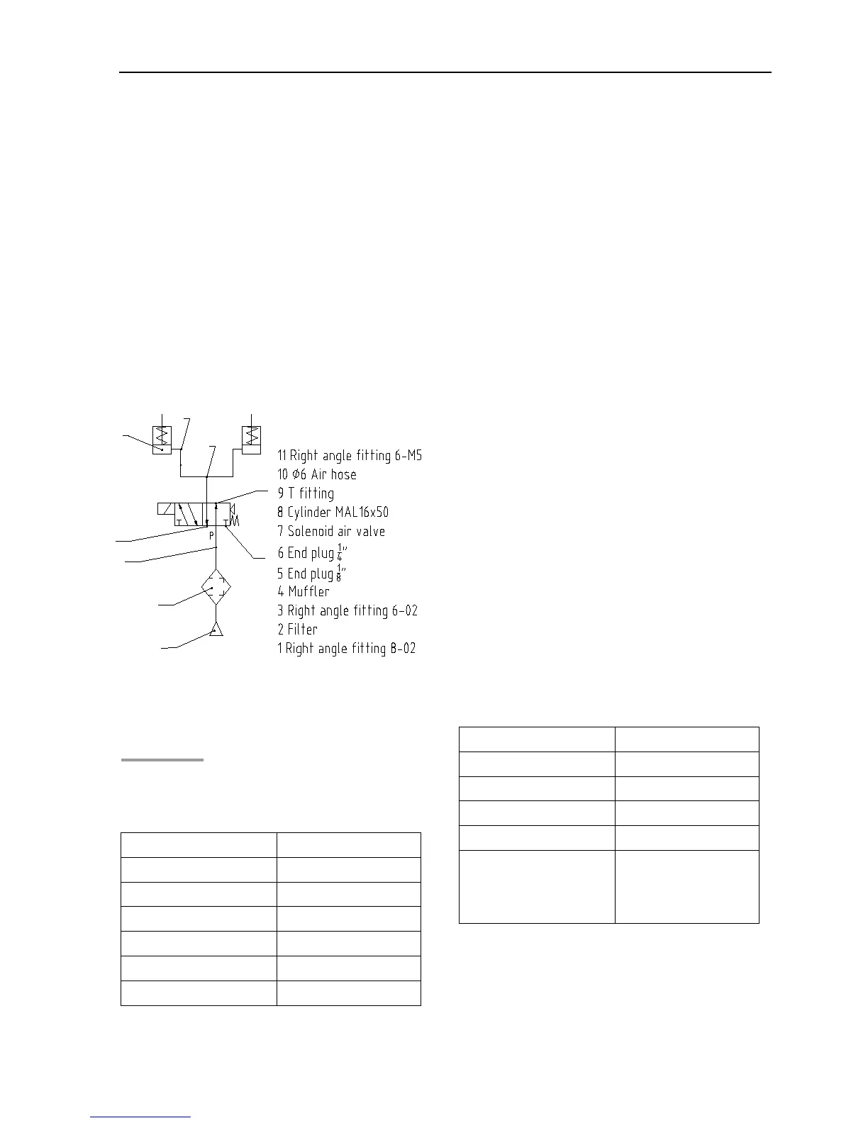
2.5 Hydraulic Components in Control Desk
8
2
6
4
7
5
3
1
9
Fig.5
3 Tools
Please get the following tools
ready for installation:
Tools
Specifications
Level Bar L=400mm15.7
Chalk Line
10mm
0.4
″)
Taper Plunger Chip
Hammer
1.5 kg(3 lb)
Crescent Wrench 40mm1.6″)
Open end Wrench Set
11mm-23mm
0.43
-0.9
″)
2mm-12mm
Screwdriver 150mm5.9″)
20mm
0.8
″)
Φ17mm
0.7
″)
Frame LevelJB3239-83 L*W*H 300mm ×
40mm× 300mm(11.8
×
0.16
″×
11.8
)

Questions and Answers:

Question and Answer IconNeed help?

Do you have a question about the Launch TLT632AF and is the answer not in the manual?

Launch TLT632AF Specifications

General IconGeneral
BrandLaunch
ModelTLT632AF
CategoryScissor Lifts
LanguageEnglish