19
ASSEMBLY
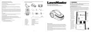
LED on the Base
Station
Status Action
Green, continuous
Boundary wire and base station are connected
successfully; the robotic mower is fully charged.
*UHHQÀDVKLQJ The robotic mower is charging.
Off No power supply.
Check the power
adaptor, cord, breakers,
and fuses.
5HGÀDVKLQJ
Power adaptor is connected successfully, while
the boundary wire is connected unsuccessfully
to the base station.
Check the boundary wire
for correct connection to
the base station.
Check the LED status as below to make sure the connection between the base station and
boundary wire is OK.
NOTE: The boundary wire must be laid anti-clockwise around the lawn. If the boundary wire is laid
clockwise around the lawn, the LED on the base station still be green continuous, but the mower is
not able to work within the boundary area.
Splice the Boundary Wire (See Figs. 26-27)
Use a coupler to extend and splice the boundary wire as needed. The coupler is waterproof and
provides optimal connection.
Ŷ,QVHUWERWKZLUHHQGVLQDQ\WZRRIWKHWKUHHKROHVRIWKHFRXSOHU)LJ
Ŷ9HULI\WKDWWKHZLUHVDUHIXOO\LQVHUWHGDQGERWKZLUHHQGVDUHYLVLEOHRQWKHRWKHUVLGHRIWKH
coupler (Fig. 26).
Ŷ8VHDSDLURISOLHUVWRSUHVVWKHFRXSOHUWRJHWKHU)LJ