41
GEAR HEAD AND SPOOL
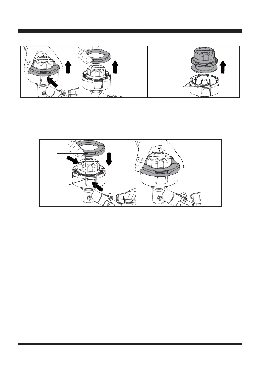
Line Replacement - Rapid Reload
TM
Spool (See Figs. 88-90)
Ŷ5HPRYHWKHHPSW\VSRROIURPWKHJUDVVWULPPHU&KHFNDQGHQVXUHWKHUHLVQRUHPDLQLQJFXWWLQJ
line in the spool.
Ŷ5HLQVWDOOWKHHPSW\VSRROWRWKHWULPPHUKHDG
Ŷ3UHVVDQGURWDWHWKHVSRROKHDGFORFNZLVHWRDOLJQWKHDUURZRQVSRROKHDGDQGWKHOLQHRQWKH
trimmer head cover as shown (Fig. 88).
NOTE:8VHRQO\URXQGPRQR¿ODPHQWOLQHZLWKWKHUHFRPPHQGHGGLDPHWHU
Ŷ(QVXUHWKDWWKHQHZFXWWLQJOLQHLVVXI¿FLHQWO\ORQJDSSUR[LPDWHO\IWPIRU´OLQHDQG
ft. (5m) for 0.095” line. First insert one end of the line into the eyelet on the trimmer head housing
and the spool in the trimmer head. Fully insert the line until you feel it stop and cannot be inserted
any further. Then insert the other end of the line into the other eyelet on the trimmer head housing
and the spool in the trimmer head. Ensure the line is fully inserted until it stops (Fig. 89).
Ŷ,QVWDOOWKHQHZVSRROLQWRWKHWULPPHUKHDG
Ŷ7RUHLQVWDOOWKHWULPPHUKHDGFRYHU¿UVWDOLJQWKHPRXQWLQJKROHVRQWKHWULPPHUKHDGFRYHUZLWK
the locking tabs on the trimmer head housing as shown. Then press the locking tabs and push the
trimmer head cover onto the trimmer head housing. Make sure they are secured tightly (Fig. 87).
Locking tabs
on the trimmer
head housing
Fig. 85 Fig. 86
Ⅰ
Ⅱ
Locking tabs on
the trimmer head
housing
Fig. 87
Ⅰ
Ⅰ
Ⅱ
Mounting
Hole

 Loading...