Rev: 07.11.2018
Page 4
CCD-0001395
Fig. 4
A
Fig. 3
B
AA
2. Align the 3 holes in the Smart Jack™ mounting plate (Fig. 3A) with the 3 holes in the coupler (Fig. 3B).
3. Secure the Smart Jack™ to the coupler with three ⁄" - 16 x 1" serrated flange grade 5 zinc coated bolts
(Fig. 4A).
4. Connect the red power wire from the Smart Jack™ housing to a grounded 12V power supply on the
trailer.
NOTE: The Smart Jack™ MUST be wired with a 30 amp in-line fused circuit.
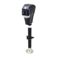
5. Reattach the footpad to the jack leg by sliding the footpad back over the bottom of the jack leg and
securing it with the previously-removed clevis pin and hairpin cotter pin.