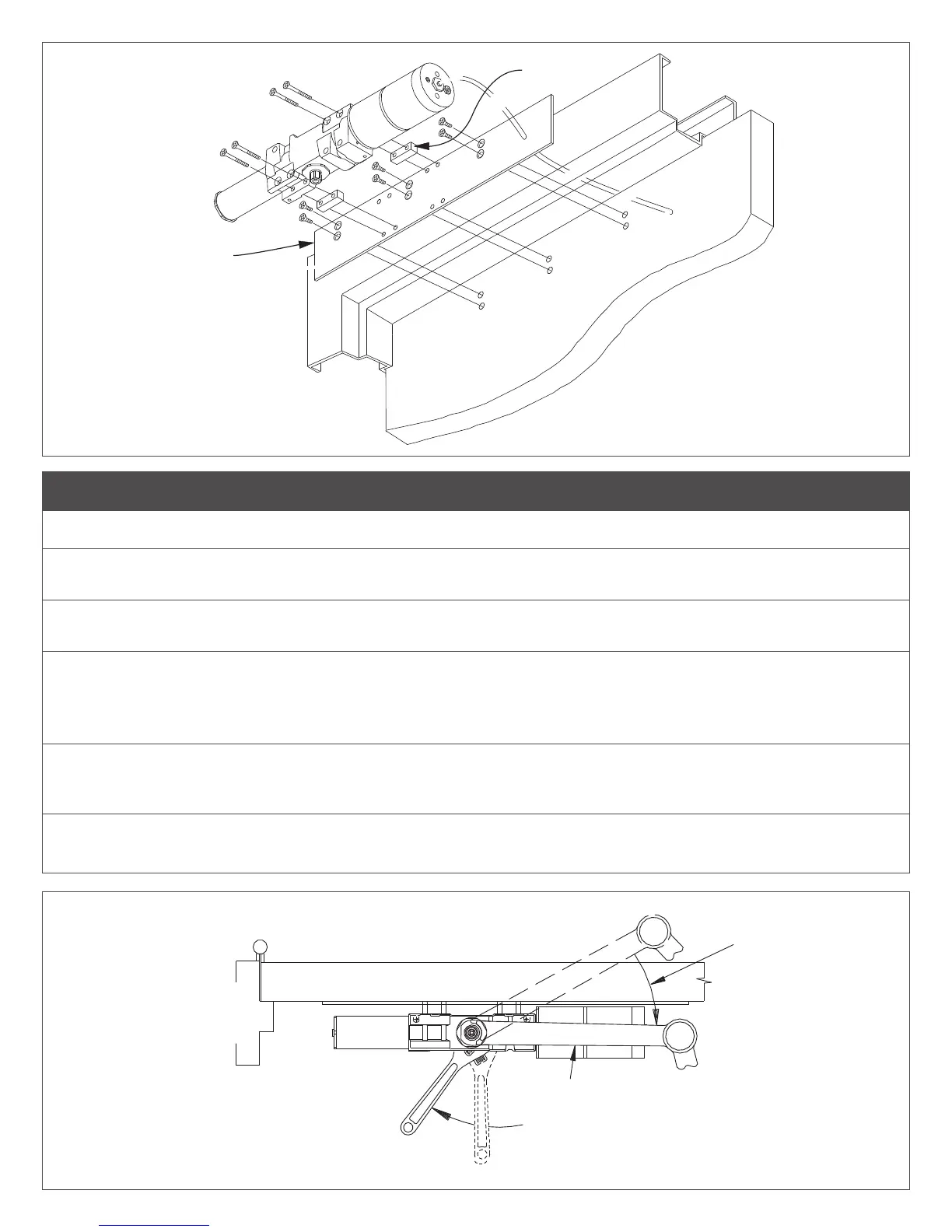
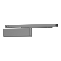
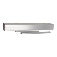
Standoff
Mounting
Plate
Figure 1
2 Operator Installation
L NOTE: If using the 460 transfer hinge, install at this time. See page 6 for details.
2a Prepare door & frame per template on page 7. Drill and/or tap holes to receive 1/4 - 20 machine screws or No. 14
wood screws. Use fasteners provided by LCN to keep warranty valid.
2b Remove operator assembly from mounting plate, as shown in Figure 1 above. Install mounting plate on door using
(6) 1/4 - 20 x 5/8” machine screws or (6) No. 14 x 1 1/2” wood screws provided. Reattach operator assembly.
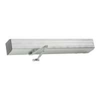
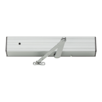
2c Place arm on the top of closer shaft with main arm parallel to the door. Place wrench on the bottom of the closer shaft
and rotate toward hinge approx. 30°. See Figure 2. Main arm can now be placed on to closer shaft. Secure with arm
screw.
L NOTE: If installed properly, main arm will rest against door.
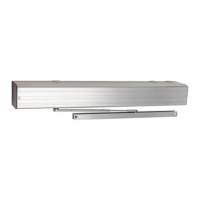
2d Swing door open about 45°. Using the fasteners provided, mount shoe to frame stop per proper templating on page 7.
Be sure to install the “fth” screw. If stop is not wide enough, use spacer block provided or cush shoe support shown
on page 7.
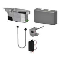
2e Connect air line to air inlet tting, then feed other end toward control box by either using the 15” pneumatic door loop
or the pneumatic transfer hinge (see page 6).
30°
Main Arm
30°
Approx.
Figure 2