EasyManua.ls Logo

LCN 4630CS User Manual

LCN 4630CS
21 pages
To Next Page IconTo Next Page
Page #1 background imageLoading...
Page #1 background image
*29268*
29268
The 4600CS Series electric Auto-Equalizer™ series combines all door
operator and door control functions in one package. This versatile,
easy-to-install system is low maintenance and offers the following
features:
Top jamb mounting on either side of an interior door allows 90°
of power opening. (Mounting for exterior door on the inside only)
Manual opening up to 170° (4630CS) or 100° (4640CS).
Quiet, reliable operator delivers consistent performance.
No expensive service contracts or periodic maintenance
required.
Fail safe operator acts as a standard door closer in event of
power outage.
Low energy operator does not require guard rails or safety mats.
Advanced, easy-to-install controller module allows independent
adjustment of:
a. Door Opening Speed
b. Delay / Trigger Time for Sequential Option
c. Door Opening Force
d. Electric Strike Delay Time
e. Hold Open Time
f. 90° Slow Down
g. Alternate Action Timeout
h. Safety Scanner Lockout Time
Table of Contents
Pg. 2 .......... General Information
Pg. 3 .......... Install Mounting Plate
Pg. 4 .......... 4630CS Template
Pg. 5 .......... 4640CS Template
Pg. 6 .......... Installing Closer Assembly
Pg.7-8......... 4600CS Series Arm Installation
Pg. 9 .......... Closer Regulation & Power Adjustment
Pg. 10 ........ Controller Installation
Pg. 11 ........ Electrical Connections
Pg.12-13..... Typical Wiring
Pg.14 ......... Auxiliary Electrical Device Wiring
Pg.15 ......... Controller Setting Adjustment
Pg. 16-17.... Controller Programming
Pg.18 ......... Basic Operation & Cover Installation
Pg.19 ......... Illustrated Parts List
4630CS, 4640CS Electric Auto Equalizer Series
4600CS Electronic Low
Energy Operator
Installation Instructions
Customer Service
1-877-671-7011 www.allegion.com/us
4640CS
PUSH SIDE MOUNT
4630CS
PULL SIDE MOUNT
Question and Answer IconNeed help?

Do you have a question about the LCN 4630CS and is the answer not in the manual?

LCN 4630CS Specifications

General IconGeneral
Power consumptionApprox. 1.5 W
Operating temperature-20 °C to +60 °C
Protection classIP54
Relay outputs2 (potential-free changeover contacts)
Max. switching voltage250 V AC
Housing materialPlastic

Summary

General Information

Codes and Standards Compliance

Lists ANSI, UL, and NEC standards the operator meets.

Door Operator Specifications and Requirements

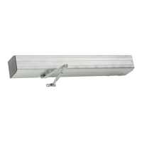
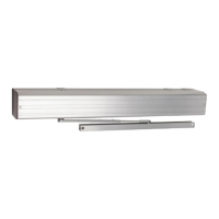
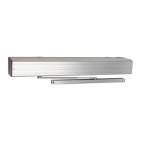
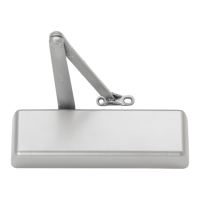
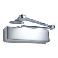
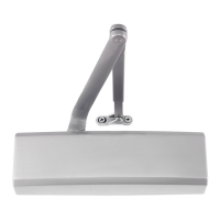
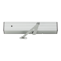
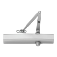
Details 4631CS/4642CS features, requirements, and limitations.

Power and Electrical Requirements

Covers voltage, current, power supplies, and system compatibility.

Section 1: Securing Mounting Plate Assembly to Frame

Conduit Connection Options

Explains concealed, surface, and top conduit wiring methods.

Mounting Plate Installation Procedures

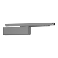
Steps for attaching the mounting channel to the frame.

Section 2: Installing Closer Assembly

Closing Force and Spring Adjustment

Guides for adjusting closing power based on door width and type.

Closer and Arm Assembly Mounting

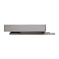
Instructions for mounting the closer body to the channel and aligning it.

4630CS Series Arm Assembly

Detailed steps for assembling the arm components for the 4630CS model.

4640CS Series Arm Assembly

Detailed steps for assembling the arm components for the 4640CS model.

Door Closer Hydraulic Regulation & Power Adjustment

Hydraulic Adjustments for Speed and Backcheck

Explains adjustments for closing speed, backcheck, and latch speed.

Safety Decal Placement and Compliance

Instructions for applying the automatic door decal for safety compliance.

Section 3: Installation & Adjustment of Controller Board

Controller Mounting Procedure

Steps for attaching the controller board to the operator assembly.

Controller Wiring Connections

Details on connecting ribbon cable, power, and motor/clutch harnesses.

Electrical Connections and Wiring

High Voltage Electrical Connections

Diagram and notes for high voltage wiring to the unit.

Low Voltage Electrical Connections

Lists functions and terminals for low voltage wiring.

Single Door Wiring Configurations

Wiring diagram and terminal assignments for single door setups.

Wiring Configurations for Multiple Doors

Simultaneous Pair Wiring Connections

Wiring diagrams for simultaneous door pairs.

Sequential Wiring - Simultaneous Vestibule

Wiring for sequential operation in a simultaneous vestibule setup.

Sequential Wiring - Independent Vestibule

Wiring for sequential operation in an independent vestibule setup.

Sequential Pair Wiring - Simultaneous Vestibule

Wiring for sequential pair operation in simultaneous vestibules.

Sequential Pair Wiring - Independent Vestibule Pairs

Wiring for sequential pair operation in independent vestibules.

Wiring for Ancillary Devices

Electronic Latching Device Wiring

Information on wiring EPT power transfer and EL devices.

Electric Strike/Mag-Lock System Wiring

Wiring diagrams for electric strikes and mag-locks.

Controller Setting Adjustments

Overview of Controller Settings and Indicators

Explains controller settings, adjustments, and indicators.

Adjusting Opening Speed and Force

Details how to adjust opening speed and force for optimal performance.

Understanding Time Display and Control Buttons

Explains the time display and UP/DOWN/MODE buttons.

Controller Programming Modes

Programmable Mode Descriptions

Details each programmable mode like Hold Open Time, Slow Down, etc.

Operating Indicator Functions

Explains the meaning of various operating indicators on the controller.

Controller Programming and Troubleshooting

Error Codes and Normal Operation Status

Lists controller error codes and normal operating indicators.

Step-by-Step Programming Guide

Step-by-step instructions for adjusting controller programming modes.

Factory Default Reset Procedure

Instructions on how to reset the controller to factory default settings.

Basic Operation and Cover Installation

Door Operator Functional Logic

Explains how the operator functions with actuators and safety inputs.

Operator Cover Installation

Steps for installing the operator cover.

Replacement Parts Information

4630CS/4640CS Main Assembly Parts List

Lists main assembly components and their part numbers.

4631CS Arm Parts List

Lists specific arm assembly parts for the 4631CS model.

4642CS Arm Parts List

Lists specific arm assembly parts for the 4642CS model.

Related product manuals