Page 8
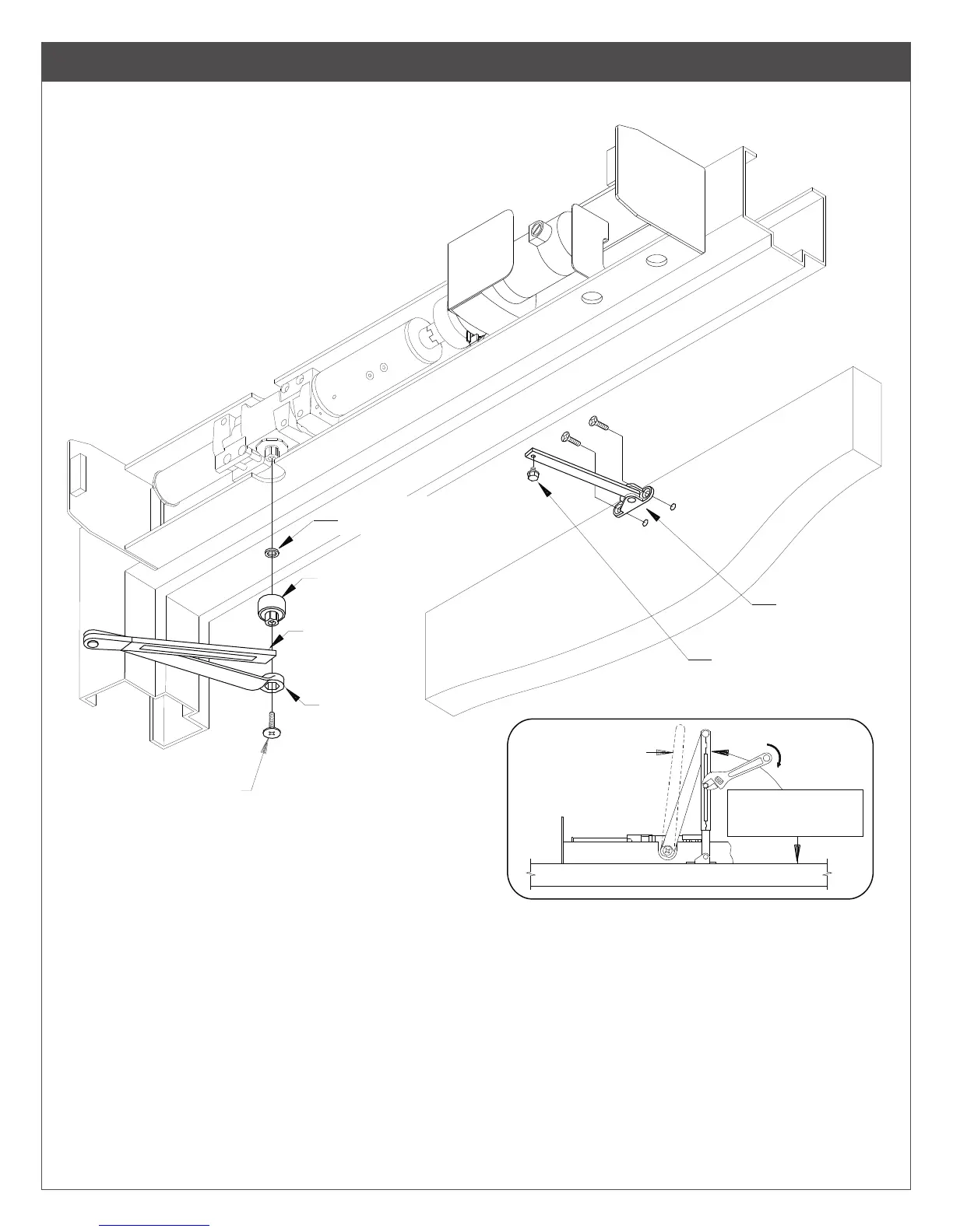
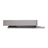
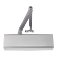
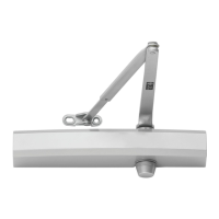
4640CS Series Arm Assembly
NOTE: Left hand door shown, Right hand will be opposite.
Fig. 7
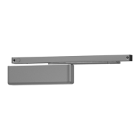
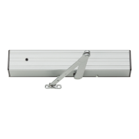
Fig. 8
5/16
" LOCK WASHER
EXTENSION
ARM
SHAFT
SCREW
ARM SET SCREW
ROD & SHOE
NOTE: Left hand door shown,
Right hand will be opposite.
Preload to 90°
as shown
FOREARM
TUBE
MAIN
ARM
1. Locate SHAFT EXTENSION, LOCK WASHER & ARM SHAFT SCREW in fastener box. Fit arm onto shaft extension. Place lock
washer into shaft extension so it will rest between closer shaft and shaft extension. Fit arm assembly over closer shaft so main arm is
positioned at approx. 90° to operator assembly and fasten with arm shaft screw, as shown in Fig. 7 above.
2. Attach rod & shoe assembly to door with (2) 1/4 - 20 x B\,”” machine screws or (2) No. 14 x 1 Z\x” wood screws provided. The longer
end of shoe should point towards hinge edge, as shown above.
3. Open door partially, insert rod into forearm tube, then close the door.
4. Insert arm set screw into rod and nger tighten. Preload arm to 90°, as shown in Fig. 8 above. Holding arm in this position, place a
wrench on arm set screw and tighten securely.
5. Proceed to REGULATION INFORMATION on page 9.