Do you have a question about the LCN ELECTRIC AUTO-EQUALIZER 4630 and is the answer not in the manual?
Details compliance with industry codes like ANSI, ADA, and UL standards.
Outlines operational features and physical requirements for 4631/4642 models.
Covers power supply needs, voltage, and compatibility with accessories.
Discusses concealed vs. surface wiring and template usage for frame prep.
Details the steps for securely attaching the mounting channel to the frame.
Explains how to properly connect and route conduit through the mounting channel.
Explains how to adjust spring power based on door width using tables.
Details the process of attaching the closer body to the mounting channel assembly.
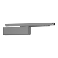
Steps for inserting track plugs and rollers into the track assembly.
Instructions for securely attaching the track assembly to the door.
Details how to connect the arm assembly to the closer shaft extension.
Describes the final connection of the arm to the track roller.
Details connecting the arm assembly to the closer shaft.
Instructions for securing the rod and shoe to the door.
Explains rod insertion and tightening the arm set screw.
Covers hydraulic regulation of opening and closing speeds.
Specific adjustment for the 4640 model's closing power at latch.
Instructions for correctly positioning the caution door decals.
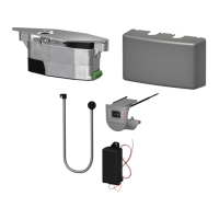
Details the process of attaching the controller unit to the operator assembly.
Explains how to connect the wiring harnesses to the controller.
Wiring diagrams and procedures for high voltage components.
Covers low voltage wiring and functional terminal assignments.
Wiring diagram for paired operators in simultaneous mode.
Wiring diagram for vestibule applications in simultaneous mode.
Wiring diagram for vestibule applications in independent mode.
Wiring diagram for paired vestibule operators in simultaneous mode.
Wiring diagram for paired vestibule operators in independent mode.
Wiring instructions for electronic latching devices using 12V/24V power.
Wiring for 24V DC and 12V DC electric strikes and mag-locks.
Explains the physical controls, indicators, and button operations.
Details how to use controls for adjusting opening speed and force.
Guides on adjusting timing parameters and programming modes.
Configuration options for door hold open duration and slow down time.
Settings for input types, exterior operation, and operational modes.
Settings for sequential, alternate action, and safety lockout delays.
How to access programming, interpret error codes, and check switch states.
Step-by-step guide for modifying each controller setting.
Procedures for saving settings, exiting programming, and performing a factory reset.
Lists maximum door opening speeds as per ANSI 156.19 standards.
Explains how actuator inputs initiate door cycles and safety checks.
Details the 'Second Chance' feature and hold open delay functionality.
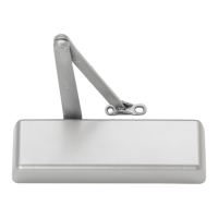
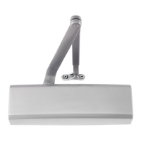
Lists specific replacement parts for the 4630 series arm assembly.
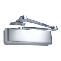
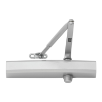
Lists specific replacement parts for the 4640 series arm assembly.
Identifies replacement components for the main operator unit.
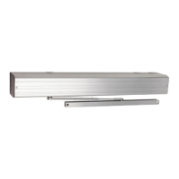
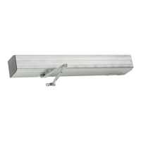
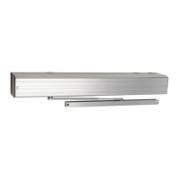
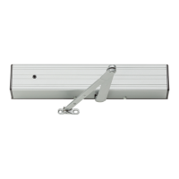
The LCN 4630/4640 Electric Auto-Equalizer Series is a versatile, low-energy door operator designed to combine all door operator and control functions into a single, easy-to-install package. This series is non-handed and non-sized, offering features typically found in heavy-duty LCN door closers, including independent adjustment of backcheck, main speed, and latch speed, as well as adjustable closing power. The units are shipped with LCN's "Ultra X" all-weather hydraulic fluid, ensuring reliable operation across a wide range of temperatures.
The 4600 Series electric Auto-Equalizer provides power opening for interior doors up to 90 degrees. For exterior doors, it must be mounted on the inside only. Manual opening is possible up to 170 degrees for the 4630 model and up to 100 degrees for the 4640 model. The operator is designed to be fail-safe, meaning it acts as a standard door closer in the event of a power outage. As a low-energy operator, it does not require guard rails or safety mats, simplifying installation and reducing overall costs.
The 4600 Series offers advanced control and adjustment capabilities through its easy-to-install controller module.
| Brand | LCN |
|---|---|
| Model | ELECTRIC AUTO-EQUALIZER 4630 |
| Category | Door Opening System |
| Language | English |