Page 6
3.
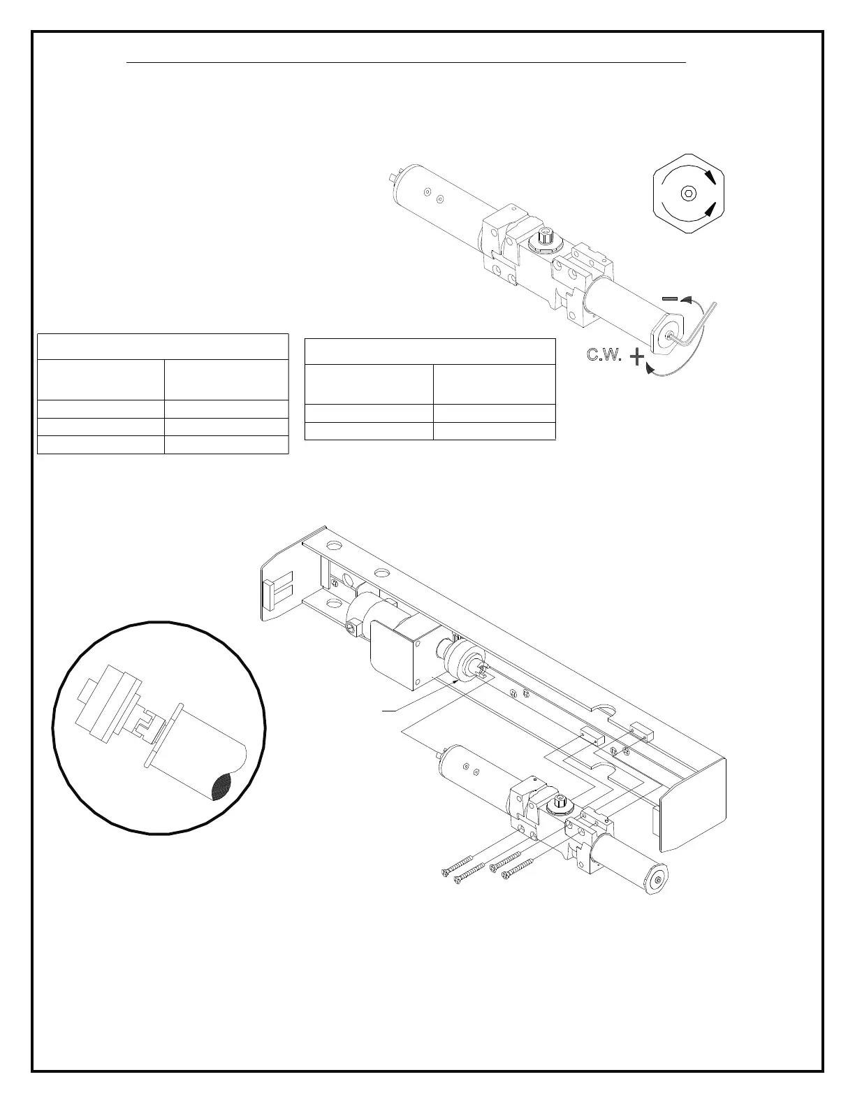
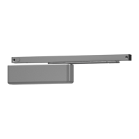
Fig. 5
Mount closer to mounting channel assembly.
Closer and clutch gear coupler's should mesh
loosely as shown in above. Line closer
mounting holes up with holes in stand-offs
attached to mounting channel. Fasten with
(4) 1/4 - 20 x 2 " machine screws provided
and tighten securely.
5/16
SECTION 2 - INSTALLING CLOSER ASSEMBLY
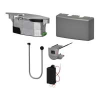
NOTE: Electrical components not shown.
Fig. 5
CLUTCH
TO INCREASE
SPRING POWER
TO DECREASE
SPRING POWER
INTERIOR DOOR
TABLE 1
MAXIMUM
DOOR WIDTH
NUMBER
OF TURNS
0
36"
48"
2 TURNS C.W.
54"
7 TURNS C.W.
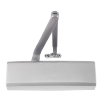
Fig. 4
C.W.
EXTERIOR DOOR
TABLE 2
MAXIMUM
DOOR WIDTH
NUMBER
OF TURNS
36"
2 TURNS C.W.
42"
7 TURNS C.W.
1.
UNPOWERED.
At this point of the installation, the mounting channel assembly should be attached securely to door
frame. All electrical connections at the unit should be hooked up, but
2. CLOSING FORCE ADJUSTMENT:
( Fig. 4).
Tables 1 & 2.
See Turn spring adjustment
clockwise the required number of
turns to match door width as shown in
Maximum adjustments:
14 turns clockwise.
4. It is extremely important that closer is properly
aligned with motor/clutch assembly.
NOTE: Do not allow any form of lubricant to come into contact with any part of clutch assembly.