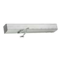
Do you have a question about the LCN 4630CS and is the answer not in the manual?
| Power consumption | Approx. 1.5 W |
|---|---|
| Operating temperature | -20 °C to +60 °C |
| Protection class | IP54 |
| Relay outputs | 2 (potential-free changeover contacts) |
| Max. switching voltage | 250 V AC |
| Housing material | Plastic |
Lists ANSI, UL, and NEC standards the operator meets.
Details 4631CS/4642CS features, requirements, and limitations.
Covers voltage, current, power supplies, and system compatibility.
Explains concealed, surface, and top conduit wiring methods.
Steps for attaching the mounting channel to the frame.
Guides for adjusting closing power based on door width and type.
Instructions for mounting the closer body to the channel and aligning it.
Detailed steps for assembling the arm components for the 4630CS model.
Detailed steps for assembling the arm components for the 4640CS model.
Explains adjustments for closing speed, backcheck, and latch speed.
Instructions for applying the automatic door decal for safety compliance.
Steps for attaching the controller board to the operator assembly.
Details on connecting ribbon cable, power, and motor/clutch harnesses.
Diagram and notes for high voltage wiring to the unit.
Lists functions and terminals for low voltage wiring.
Wiring diagram and terminal assignments for single door setups.
Wiring diagrams for simultaneous door pairs.
Wiring for sequential operation in a simultaneous vestibule setup.
Wiring for sequential operation in an independent vestibule setup.
Wiring for sequential pair operation in simultaneous vestibules.
Wiring for sequential pair operation in independent vestibules.
Information on wiring EPT power transfer and EL devices.
Wiring diagrams for electric strikes and mag-locks.
Explains controller settings, adjustments, and indicators.
Details how to adjust opening speed and force for optimal performance.
Explains the time display and UP/DOWN/MODE buttons.
Details each programmable mode like Hold Open Time, Slow Down, etc.
Explains the meaning of various operating indicators on the controller.
Lists controller error codes and normal operating indicators.
Step-by-step instructions for adjusting controller programming modes.
Instructions on how to reset the controller to factory default settings.
Explains how the operator functions with actuators and safety inputs.
Steps for installing the operator cover.
Lists main assembly components and their part numbers.
Lists specific arm assembly parts for the 4631CS model.
Lists specific arm assembly parts for the 4642CS model.
 Loading...