740100-00(5) Page 5 of 14
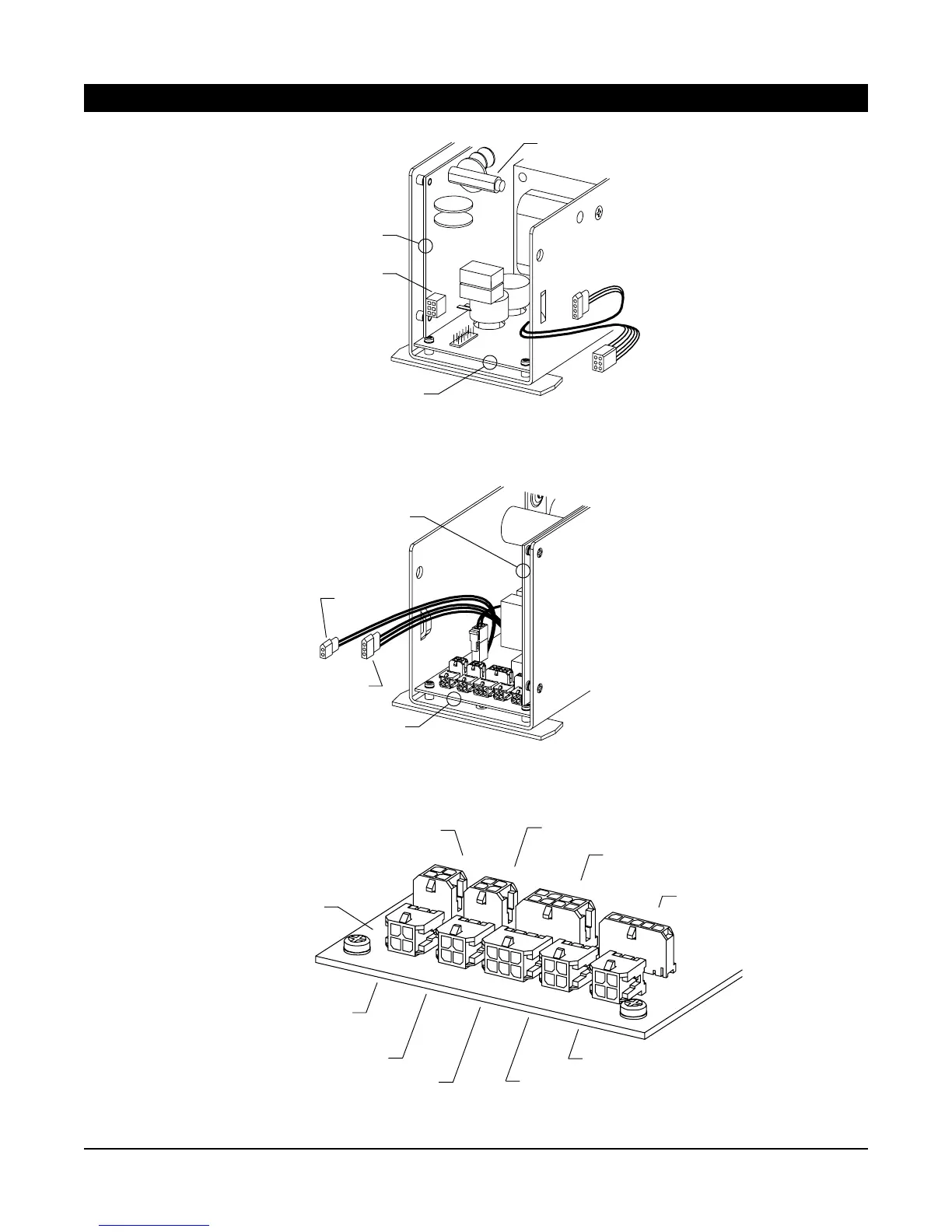
Figure 3-2. Control box power board connectors.
3. WIRING (continued)
Figure 3-3. Control box logic board connectors.
Figure 3-4. Closeup of control box logic board connectors.
P5
P3
P2
P1
P6
P7
P4
P10
P8
DMSS (companion; safety side)
Activate
Activate
DMSS (master; safety side)
DMSS (master; approach side)
DMSS (companion; approach side)
LOGIC BOARD
Companion
motor power
(P5)
POWER
BOARD
LOGIC BOARD
AC fuse, 120 VAC
2.5 A time-delay
Master motor
power
AC
power
Bodyguard (safety side)
Breakaway
3-position
switch
POWER BOARD
LOGIC BOARD
See Figure 3-4 for
closeup of control
box logic board
connectors
Locking Interface and
Power Boost disable input
Retrofit
Accessories
 Loading...