Do you have a question about the Leader 192A and is the answer not in the manual?
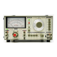
Details frequency range, calibration accuracy, output characteristics, and controls for the audio generator.
Covers square wave output, impedance, and SYNC signal terminal specifications.
Details voltage range, decibel range, accuracy, and frequency range for the AC millivoltmeter.
Explains meter, zero adjuster, range selection, and input terminals for the AC millivoltmeter.
Details attenuator switches, output impedance, output jacks, ground terminal, and frequency range controls.
Describes SYNC terminals, AC inlet, fuseholder, serial plate, and output terminals on the rear panel.
Covers initial checks, precautions, and control adjustments for the AF signal generator.
Details precautions, preparation steps, voltage measurements, and decibel measurements for the AC millivoltmeter.
Explains how to use attenuators and provides input/output characteristics for typical applications.
Provides guidance on fuse ratings and replacement procedures for different power voltages.
| Brand | Leader |
|---|---|
| Model | 192A |
| Category | Test Equipment |
| Language | English |