Do you have a question about the Leader LBO-51MA and is the answer not in the manual?
Details deflection sensitivity, accuracy, bandwidth, rise time, linearity, and input coupling for vertical and horizontal amplification.
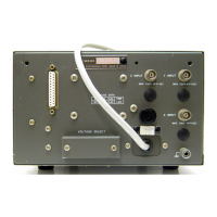
Covers power requirements, consumption, dimensions, weight, operating, and storage temperatures of the instrument.
Outlines general calibration requirements, warm-up period, and safety precautions for servicing.
Specifies the initial settings for various controls prior to performing calibration adjustments.
Details the procedure for checking and adjusting the internal power supply voltages.
Covers the adjustments for intensity and focus to achieve optimal CRT display clarity.
Details bias, DC balance, sensitivity, and frequency response adjustments for the Y-axis amplifier.
Details bias, DC balance, sensitivity, and frequency response adjustments for the X-axis amplifier.
Explains the procedure for adjusting the X-Y phase to ensure proper display alignment.
Covers the adjustment procedure for the Z-axis input and frequency response.
General checks including equipment, control settings, visual defects, and initial adjustments.
Focuses on checking major oscilloscope sections: HV power supply, Y-axis, and X-axis amplifiers.
Provides systematic steps for diagnosing issues like no spot, axis deflection, or low sensitivity.
Diagram illustrating the locations of adjustment controls and test points on the right side.
Diagram illustrating the locations of adjustment controls on the left side of the unit.
Component layout diagram for the main T-2510 printed circuit board.
Component layout diagram for the T-2511 X, Y pre-amplifier printed circuit board.
Component layout diagram for the T-2512 CRT control printed circuit board.
Component layout diagram for the T-2513 X, Y control printed circuit board.
Schematic diagram illustrating the power supply circuit of the LBO-51MA instrument.
Schematic diagram for the CRT and Z-AXIS amplifier sections of the oscilloscope.
Schematic diagram for the X, Y pre-amplifier circuit board (T-2511).
Schematic diagram for the X, Y final amplifier circuits.
List of components, including resistors, diodes, and ICs, for the T-2510 main board.
List of components for the T-2511 X, Y pre-amplifier board, including resistors and capacitors.