7.2 ADJUSTMENT OF METER ZERO WITH
POWER ON
1 .
+25V
range
a. Turn the pcjwer on.
b. Push the REFERENCE
H-25V
METER selector button
(
3
)
,
c. On circuit board T-2665A, adjust
VR502
(0
ADJ) until
the
voltmeter
indicates
zero.
2.
-25
V
range
a. Push the TRACKING —25V METER
selector
button
(4)
.
b. On circuit board T-2665A, adjust VR504
(0
ADJ) until
the voltmeter indicates zero.
3.
+6V
range
a. Push the +6V METER selector button
(5).
b.
On
circuit
board T-2665A,
adjust
VR506
(0
ADJ) until
the voltmeter indicates zero.
7.3 ADJUSTMENT OF THE VOLTMETER
WITH POWER ON
1.
T
25V range
Push the REFERENCE
+25V
METER selector button
(3)
.
b.
Connect
a
known
calibrated
voltmeter
across
the
+25V
output
(
+
)
and COM
(
—
)
terminals.
c. Set the REFERENCE/± 25V control
so
that
the
volt-
meter reads 25.0Vdc.
d.
On circuit
board
T-2665A,
adjust
VR501
(VOLTS)
so
that the voltmeter indicates 25V.
2.
—25
V
range
a.
Pu.sh the
TRACKING
“25V METER
selector
button
(4)
.
b.
Connect a known calibrated voltmeter across the —25V
output
(+)
and COM (-) terminals,
c. Confirm that the voltmeter and the power supply volt-
meter both
indicate
—25V.
3. +6V range
a.
Push
the
T6V
METER selector
button
(5).
b. Connect a
known
calibrated
voltmeter
across the
+6V
(+)
and
COM
(—
)
terminals.
c. Use the
+6V
voltage control to make the voltmeter indi-
cate
6.0Vdc. The
power
supply
voltmeter
should indi-
cate 6
volts.
7,4
AMMETER
ADJUSTMENTS
1. +0.5A range
a.
Push
the REFERENCE +25V METER selector button.
b.
Set
the +0.5A (lA for the EPS-
152)
CURRENT
con-
trol fully
clockwise.
c. Connect a
known
calibrated
ammeter and a 12.5W
(25
W for the LPS-
152)
rheostat as shown in
Figure
7-1
.
d. Set the REFERENCE/±
25V control so that the voltme-
ter
indicates
25V.
e. Adjust the rheostat so that
the
installed
ammeter indi-
cates 0.5A
(
1 .OA for
the
EPS-
152).
f.
On
circuit board T- 2665
A,
adjust
VR503
(FULL
SCALE) for a reading
of
+0.5A
(
1 .0 A for the LPS-
152)
on
the
power
supply ammeter,
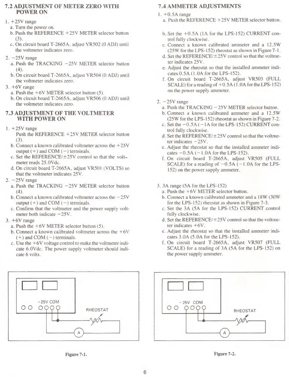
2. —25V range
a.
Push
the
TRACKING “25V METER selector button,
b. Connect a known
calibrated
ammeter
and
a 12.5W
(25W for the LPS
-
1
52)
rheostat as shown in Figure
7-2,
c. Set the
-0.5
A
(
-
lA
for the
LPS-
1
52)
CURRENT
con-
trol fully clockwise.
d. Set
the
REFERENCE/
±
25V
control so that the
voltme-
ter indicates
—25V.
e. Adjust the rheostat so that the installed ammeter indi-
cates -0.5
A
(-
1 ,0A for the LPS-
152).
f. On circuit board T-2665A, adjust VR505 (FULL
SCALE)
for
a
reading of —0.5
A (
—
1 OA for the LPS-
152)
on the power supply ammeter.
3. 3 A range (5A for the LPS-
152)
a. Push the +6V METER selector button.
b. Connect a
known
calibrated ammeter and a
18W (30W
for the LPS-
152)
rheostat as shown in Figure
7-3.
c. Set the 3
A
(5 A
for
the
LPS-
152)
CURRENT
control
fully clockwnse,
d. Set the
REFERENCE/
± 25V control so that the voltme-
ter indicates +6V.
e. Adjust the
rheostat
so
that the installed ammeter indi-
cates 3.0
A
(5.0A for the EPS- 1
52).
f. On circuit board T- 2 665
A,
adjust
VR507
(FULL
SCALE) for a reading of 3A (5A for the EPS-
152)
on
the
power
supply
ammeter.
^1
p
n
-
25V CO\
00
099c
RHEOSTAT
Figure
7-1,
6
 Loading...