2
(-)
DC ground
Use 14ga. wire
Communications Port
for second station. See
Installation Manual
for details.
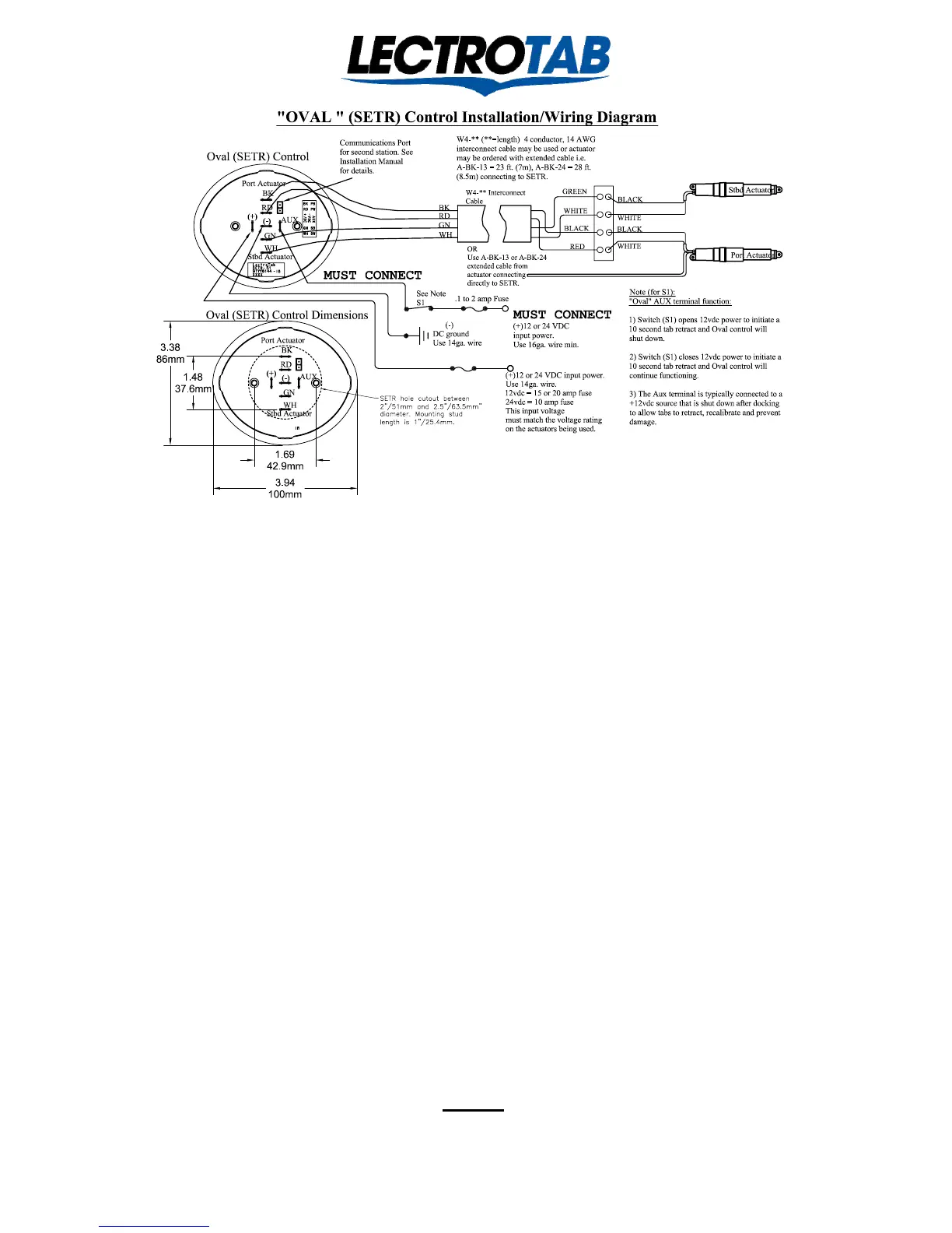
"OVAL " (SETR) Control Installation Diagram
(+)12 or 24 VDC input power.
Use 14ga. wire.
12vdc = 15 or 20 amp fuse
24vdc = 10 amp fuse
This input voltage
must match the voltage rating
on the actuators being used.
Note:
"Oval" AUX terminal function:
1) Switch (S1) opens 12vdc power to initiate a
10 second tab retract and Oval control will
shut down.
2) Switch (S1) closes 12vdc power to initiate a
10 second tab retract and Oval control will
continue functioning.
3) The Aux terminal is typically connected to a
+12vdc source that is shut down after docking
to allow tabs to retract, recalibrate and prevent
damage.
(+)
(-)
AUX
BK
RD
GN
WH
GREEN
WHITE
BLACK
RED
BLACK
WHITE
BLACK
WHITE
Stbd Actuator
W4-** Interconnect
Cable
Port Actuator
BK
RD
GN
WH
W4-** (**=length) 4 conductor, 14 AWG
interconnect cable may be used or actuator
may be ordered with extended cable i.e.
A-BK-13 = 23 ft. (7m), A-BK-24 = 28 ft.
(8.5m) connecting to SETR.
Oval (SETR) Control
(+)12 or 24 VDC
input power.
Use 16ga. wire min.
.1 amp Fuse
See Note
S1
OR
Use A-BK-13 or A-BK-24
extended cable from
actuator connecting
directly to SETR.
Port Actuator
Stbd Actuator
1. The “Oval” will fit nicely into a 2” to 2 ½ “diameter hole.
2. Wire the “Oval” as noted above. If the actuator wires will not reach the control, extend them with AWG # 14
wire. Lectrotab extending cable is color coded black, red, green and white, with recommended connections as
follows, BLACK - port actuator black. RED - port actuator white. GREEN - starboard actuator black. WHITE -
starboard actuator white.
- IMPORTANT -
DO NOT power the “Oval’s” AUX terminal directly from the trim tab fuse or circuit breaker,
or from the + terminal on the “Oval”. If the AUX terminal is powered from the + terminal on
the “Oval”, the “Oval” can only be turned off by turning off the main trim tab power. But, with no
input power, the tab 10 second calibration sequence to synchronize the tabs and indicators at full retract
CAN NOT WORK. No harm done, but the feature is lost. Wire the Aux terminal as noted above. For more
Aux terminal wiring options, see page 8 of the “Oval” installation manual # J1107.
3. Power up the vessel’s D.C. service and turn the tab circuit breaker on. Immediately, use a voltmeter to confirm
the correct polarity on the “Oval’s” + and – terminals. If incorrect, fix it. If the polarity is reversed, and the
power remains on, the “Oval” will gradually overheat. With polarity correct, the “Oval” will be in standby mode
with no LED’s Lit.
4. Provide 12 or 24 VDC power, depending on the voltage rating of the actuators being used, to the AUX terminal
from an existing switch or install a dedicated “Trim Tab” switch. See page 8 of the “Oval” manual, for more
AUX switch options. Turn this switch ON and the “Oval” will show blinking LED’s, which denotes tabs up, and,
whether the tabs themselves are up, down, or in between, the “Oval will initiate a 10 second calibration sequence
in order to synchronize the tabs and the indicators at full retract, ready for use.
5. Use the “Oval” in the conventional manner per the “Operating Guide” section on the reverse side.
6. At trip’s end, when the switch which is connected to the AUX terminal is turned OFF, the “Oval” will initiate
another 10 second calibration sequence to synchronize the tabs and the indicators at full retract, after which, the
“Oval” will revert to standby with no LED’s illuminated. Standby power is 20 milliamps and goes off completely
with the main trim tab input power.
NOTE
The “Oval” is shipped programmed for 8 second stroke time actuators. If 4 or 6
second actuators are being used, the “Oval” must be programmed accordingly for
the position indicators to be correct. This can be done in the field, See page 7!
Lit # J1107
Revised January 2014
 Loading...