4
The “Oval” Description
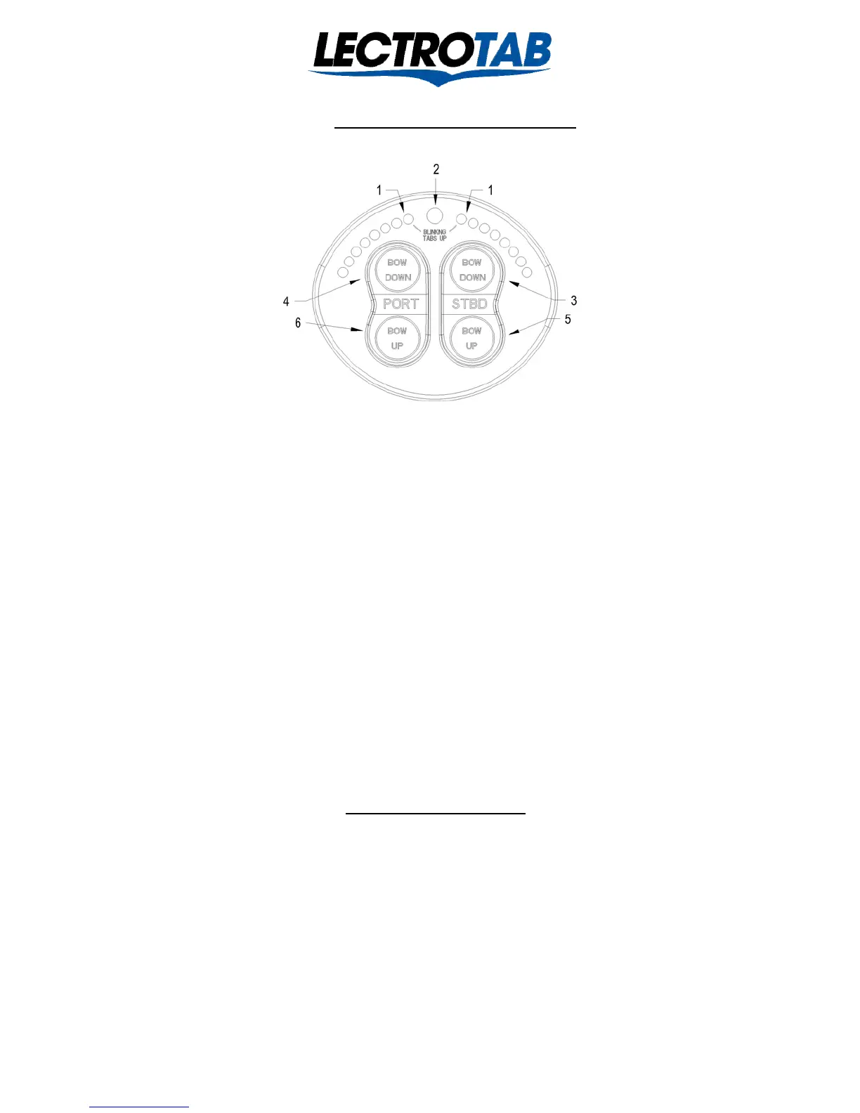
The SETR-Model SETR-61 “Oval” control operates as described below:
1 Two tab position indicators display left and right tab positions on two separate sets of LEDs. One Blinking LED at the top
indicates the tab on the other side is fully retracted as indicated by “Blinking Tabs Up” printed on the face of the control.
2 Photocell senses light level to automatically dim the trim indicator LEDs as daylight fades.
3 For Starboard Bow Down trim control, push the top of the starboard switch until the click is felt. The port tab will deploy
and the right hand indicator will show the tab position.
4 For Port Bow Down trim control, push the top of the port switch until the click is felt. The starboard tab will deploy and the
left hand indicator will show the tab position. Pushing both Bow Down buttons simultaneously will deploy both tabs and the
indicators will show both tab positions.
5 For Starboard Bow Up trim control, push the bottom of the starboard switch until the click is felt. The port tab will retract
and the right hand indicator will show the tab position.
6 For Port Bow Up trim control, push the bottom of the port switch until the click is felt. The starboard tab will retract and the
left hand indicator will show the tab position.
*Pushing both buttons simultaneously will retract or deploy both tabs. Also, the tabs may be simultaneously moved in opposite
directions if need be. The right indicator will move with the left tab; the left indicator moves with the right tab. However, the left
switch moves the right tab and the right switch moves the left tab. See page 7 for field programming of indicator timing for use
with 4, 6, or 8 second stroke time actuators. The “Oval” is shipped programmed for 8 seconds actuators.
“Oval” Installation
Tools: Ordinary hand tools, mechanical and electrical, silicone sealer (don not use 3M 5200; use only silicone sealer), a drill motor,
and a hole saw between 1-3/4” and 2-1/2”, but 2-1/16” works best. The “Oval” is designed for wet or dry locations. The Oval will
need console space of 4” wide by 3-7/16” high. Allow for a minimum of 1” clearance depth behind the OVAL. When the center of
location is determined, use a hole saw to make a 1 ¾” to 2 ½” diameter hole in the console, being careful not to cut any wires behind
the console. Use a small amount of silicone sealer around the edge of the Oval control, align to the desired orientation, and place the
control in the mounting hole. Use the special bracket and self-locking 8-32 nuts to secure the control to the console using a 11/32” or
9mm socket. Torque lightly. If access to the back of the Oval is not handy after the Oval is in place, route the 7 wires which connect
to the Oval through the hole and make the connections before securing the Oval in the hole. If the installation includes remote Oval’s,
in addition to the seven basic wires, the two conductor communications cable will need to be connected also. In a single station
installation, the two conductor communication’s cable is not used. The Oval may be installed in wet or dry locations.
Lit # J1107
Revised January 2014
 Loading...