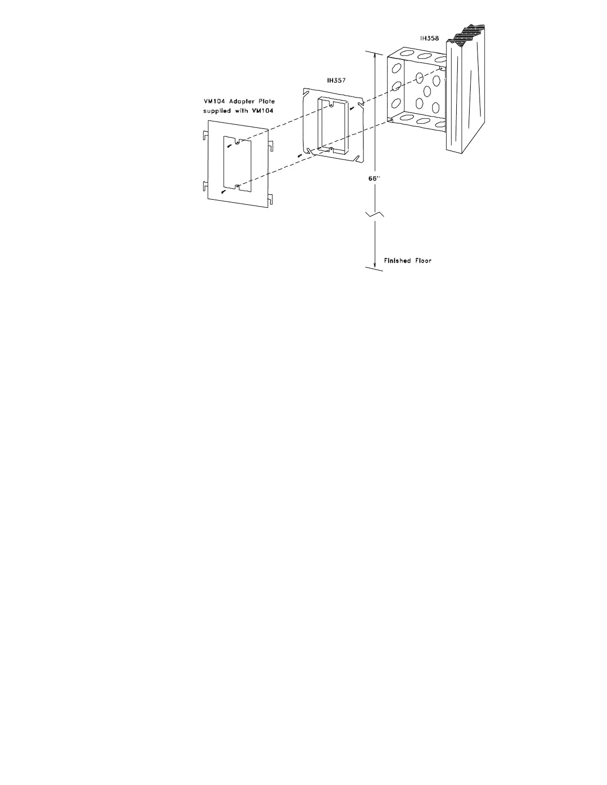
FIGURE 3 - IH-357 & IH-358
Video Monitor Box Adapter Plate
VM-104
SYSTEM LAYOUT
A. Maximum number of VM-104 monitors per PK-314A is 50 units. Only one PK-314A control unit used per system.
B. Each additional 80 VM-104 monitors require a PK-311 control unit and PS-250 transformer. (See Figure 8 for PK-311 wiring and installation instructions.)
C. Up to three separate VM-300/4T entrance panels may be used per system, following the above guidelines for each entrance panel used. (See Figures
6 and 7 for wiring instructions.)
WIRING INSTRUCTIONS
Run wires according to WIRING LAYOUT DIAGRAM (FIG. 4) in conjunction with the following notes.
A. Each VM-104 is supplied with a (CT-133) RG-59U connector board for RG-59U cable.
B. The maximum number of VM-104 monitors per riser is 20. The maximum length of each riser is 200 feet.
C. The back of VM-104 provides connecting terminals for the following. Terminals functions are as follows:
1 and 2 :Microphone for handset connects to 1,2 on PK-314A.
3 and 4 :Receiver for handset connects to 3,4 on PK-314A.
X : Ring terminal. (Selective wire which connects to individual push button at entrance for ringing unit 1 KHz tone signal. Also detects
tone and turns monitor control circuits on for 1 minute.)
C.T. :Control terminal. (When terminal X detects a tone, C.T. also goes high [approx. 10-12 VDC]). This system common connects to
C.T. at PK-314A which turns power on to camera via CP and CN.
+ :+17 VDC for connection to PK-314A terminal P.
- :Ground for connection to PK-314A terminal N.
V : Video Innput
G : Video Ground
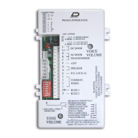
D. The CONTROL UNIT (PK-314A) provides connecting terminals with the following functions:
1 and 2 : Input from microphone of VM-104 handset. Balance input.
3 and 6 : Audio output to receiver on VM-104 handset.
M and G : Microphone input located at entrance panel (VM-300/4T). Polarity sensitive.
Z : 1 KHz OCS tone output for ringing monitors.
W :Reset terminal for power supply. Shorting this terminal to - will interrupt +17 VDC for approx. 2 seconds.
S and C :Audio output to speaker at entrance panel (VM-300/4T).
E :Post office key lock input. Shorting to C terminal will give door strike output on L (16VAC).
L :Door strike output 16 VAC 1 AMP.
N :- Neg. for +17 VDC.
P :+17 VDC output for monitors @ 3 amp maximum regulated.
T1 and T2 :16 VAC input 160 VA
C.T. :Control terminal common voltage coming from monitors C.T. terminal. Energizes relay for camera output voltage CP and CN.
CP :+15 VDC output for camera. Voltage is only present when C.T. terminal has approximately 10-12 VDC.
CN : Ground for camera voltage.
E. The DISTRIBUTION AMPLIFIER (PK-320) provides connecting terminals with the following functions:
A,G :Termination resistor jumper (short if J102 is not feeding another PK-320) or (leave open if connecting to another PK-320)
J101 : Input terminal for connection from camera output.
J103 : Video output terminal for one riser.
B :Common connection for turning system on. (Connects to PK-314A control unit terminal C.T.)
A :Common connection for turning on PK-320. (Connects to all VM-104 monitors receiving video feed from PK320.
J102 : Video output terminal to other PK-320’s. (Comes directly from camera output.
J106, J107, J108 :Video output terminals for one riser each.
 Loading...