Do you have a question about the Leeson 174603 and is the answer not in the manual?
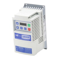
Details the items included with the SM2 Vector inverter package, emphasizing checking for completeness.
Covers general safety rules for LEESON controllers, including live parts and hot surfaces.
Ensures proper handling, avoiding stress on components, and adherence to electrical safety regulations.
Warns against using the drive as a safety device and highlights its built-in protection features.
Explains the meaning of signal words (DANGER, WARNING, STOP, Note) and associated safety icons.
Covers UL warnings for integrated systems and critical operation dangers.
Details conformity, approvals, input voltage, humidity, temperature, vibration, earth leakage, and protection measures.
Introduces the rating tables for different drive models.
Lists specifications for 120VAC and 240VAC models, including power, voltage, and current.
Lists specifications for 240VAC models, including power, voltage, and current.
Lists specifications for 480VAC and 600VAC models, including power, voltage, and current.
Provides guidelines for reducing output current based on altitude, temperature, and carrier frequency.
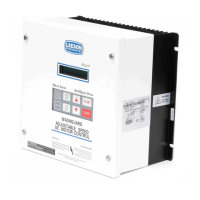
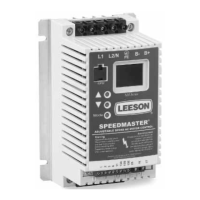
Details the physical dimensions and mounting requirements for the drive unit.
Warns against installing the drive in environments with hazardous vapors, dust, moisture, or excessive vibration.
Safety warnings and wiring diagrams for connecting mains power to the drive.
Wiring diagram for connecting 120VAC single-phase power to specific drive models.
Wiring diagrams for connecting 240VAC single-phase power to various drive models.
Wiring diagram for connecting three-phase power to all relevant drive models.
Illustrates the wiring diagram for connecting the motor to the drive's output terminals.
Specifies torque and size requirements for mains and motor terminal connections.
Guidance on circuit breakers/fuses and input power wiring sizes based on drive type.
Notes on installing Ground Fault Circuit Interrupters (GFCIs) with the controller.
Details the function, possible settings, and important notes for each control terminal.
Configuration of digital inputs for active-high or active-low using the switch and parameter P120.
Describes the functions of the keypad buttons and indicating LEDs for drive operation and programming.
Highlights critical warnings related to keypad operation, such as JOG mode and rotation direction changes.
Explains how the drive display shows output frequency, PID setpoint, or torque in different operating modes.
Overview of changing parameters using the keypad, showing status/fault messages and navigation.
Details the function of the EPM for storing settings and its capabilities for copying and modifying parameters.
Covers core setup parameters like Start Control Source and Standard Reference Source.
Defines how the drive receives start commands (keypad, terminal strip, network).
Sets the default speed or torque reference when no Auto Reference is selected.
Details parameters for frequency limits, acceleration/deceleration times, and motor overload settings.
Sets the maximum output frequency, with a warning for overspeeding.
Configures the motor thermal overload protection based on motor and drive ratings.
Covers start methods, stop methods, and motor rotation direction settings.
Defines how the drive starts, including normal, auto-restart, and flying start options.
Specifies how the drive stops, such as coasting or using DC braking.
Configures digital input assertion level and assigns functions to TB-13A, TB-13B, TB-13C terminals.
Ensures the Assertion Level switch and P120 setting match for proper digital input operation.
Assigns functions like Auto Reference, Control Select, and Network Enable to specific input terminals.
Covers acceleration/deceleration times, auxiliary ramps, and preset speed settings.
Sets secondary acceleration and deceleration times, used with specific I/O configurations.
Configures up to seven preset speed values that can be selected via digital inputs.
Defines the function of the relay output, such as Run, Fault, or At Speed indication.
Specifies various conditions that can energize or de-energize the relay output terminals.
Configures the TB-14 output function and parameters for detecting and responding to loss of load.
Sets up scaling for analog outputs (TB-30) for frequency, load, torque, and power.
Configures speed limits for analog inputs and applies a filter to reduce signal noise.
Sets output frequencies corresponding to 0% and 100% of the analog input signal.
Adjusts the carrier frequency to manage motor noise and efficiency, with derating considerations.
Details base frequency, boost, and slip compensation settings.
Sets the motor's rated base frequency, crucial for accurate speed control.
Adjusts slip compensation to maintain motor speed under varying load conditions.
Covers current limit, DC brake settings, display scaling, and run screen display options.
Sets the maximum current limit for the drive, affecting performance and protection.
Configures DC braking parameters for stopping the motor, with specific exceptions noted.
Defines frequency ranges to be skipped to avoid mechanical resonance.
Sets the start points for frequency ranges that should be skipped during operation.
Enables PID mode, selects feedback source, and sets decimal point for display.
Activates or disables PID control and selects between normal and reverse acting modes.
Specifies the analog input (TB-5 or TB-25) used for PID feedback.
Sets feedback signal limits, proportional, integral, and derivative gains for PID loop tuning.
Defines the minimum and maximum values of the PID feedback signal.
Configures the gains for the PID control loop to achieve desired performance.
Sets PID setpoint ramp time and defines alarm thresholds for feedback signals.
Smooths transitions between PID setpoints, especially when using preset setpoints.
Sets the lower and upper limits for PID feedback alarms.
Configures preset PID setpoints and parameters for sleep mode operation.
Assigns specific PID setpoints to digital inputs for selection.
Sets conditions for entering and exiting sleep mode based on speed and bandwidth.
Chooses the motor control strategy, including V/Hz and Vector modes.
Selects V/Hz or Vector modes, with Vector modes requiring motor data and calibration.
Enters motor nameplate data such as voltage, current, frequency, speed, and cosine phi.
Configures motor resistance, inductance, torque limit, current/speed loop gains, and auto-calibration.
Sets the maximum output torque for the drive when operating in Vector Torque mode.
Initiates and manages the motor auto-calibration process required for Vector modes.
Configures the communication protocol for network operation, depending on installed modules.
Introduces diagnostic parameters for monitoring drive status and troubleshooting.
Accesses fault logs, software version, and drive ID for troubleshooting.
Monitors various drive states including internal code, voltages, load, current, torque, and temperature.
Displays the current DC bus voltage of the drive.
Displays the actual motor current being drawn by the drive.
Displays the actual values of analog inputs and scaled feedback signals.
Shows the actual value of the signal received on the 0-10 VDC input terminal (TB-5).
Displays the TB-5 signal value scaled into PID feedback units.
Displays analog output, actual output frequency, and network command speed.
Shows the current output frequency of the drive.
Indicates the status of control terminals and drive protection features via LED segments.
| Enclosure | TEFC |
|---|---|
| Speed | 1800 |
| Phase | 3 |
| Input Phase | 3 |
| Output Phase | 3 |
| Frequency | 60 |
| Voltage | 230 |
| Input Voltage | 230 |
| Output Voltage | 230 |