Do you have a question about the LEGRAND tynetec Reach IP and is the answer not in the manual?
Makes an emergency call.
Cancels an emergency call made in error.
Toggles Home/Away mode if enabled.
Powers unit on/off and enters Control/Service Menu.
Indicates unit status: no signal, alarm, or fault.
Includes 5V DC input, Programming, and Ethernet ports.
Wearing option using a neck cord with safety break.
Wearing option using a wrist strap.
Wearing option using a belt clip.
Procedure for initiating an alarm call and cancellation.
Functions for toggling illumination, changing volume, and entering Service Menu.
Functions for adding/deleting devices and setting Home/Away mode.
Turns the Red Alarm Button illumination on or off.
Adjusts the unit's speech and sound volume levels.
Procedure to register new radio devices with the Reach IP unit.
Tests signal strength for peripherals like pendants or fall detectors.
Indicates GSM signal strength via the Status LED during Range Test Mode.
Process for removing registered radio devices from the unit.
Procedure to remove all previously registered radio devices.
Enables or disables the Home/Away mode toggle via the Function Button.
Guidelines for operating temperature, sunlight, dust, moisture, and physical handling.
Instructions for cleaning the Reach IP unit and its accessories with mild soap.
Key safety precautions including testing, moisture, and system integration.
Guidance on proper disposal of the product as WEEE compliant electronic equipment.
The Tynetec Reach IP is an at-home alarm unit designed for trusted technology and caring for people, offering an emergency call system with various wearing options and user-friendly features.
The Reach IP unit serves as a central hub for an emergency call system. When activated, it initiates an alarm call to an Alarm Receiving Centre (ARC). The system includes a main alarm unit, an AC adapter, and a choice of a Touch Pendant or a Wrist Worn Fall Detector for triggering alarms. It supports both UK and EU mains plug options. The unit can be mounted flat using a connector cover or vertically with a stand.
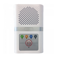
The main unit features several buttons and an LED indicator. The Red Alarm Button is used to make an emergency call. The Green Cancel Button allows users to cancel an emergency call in progress and adjust speech and sound volumes. The Yellow Function Button toggles Home/Away mode (if enabled) and provides access to the Service Menu. The Black Power Button turns the unit on/off and enters Control Mode/Service Menu. The Status LED indicates the unit's operational status: off for normal, green for no signal, red for alarm, and amber for fault.
The Touch Pendant is a portable alarm trigger that can be worn around the neck, on the wrist, or clipped to a belt. It is pre-registered to the Reach IP unit and ready for immediate use. When the pendant button is pressed, it flashes red to indicate transmission and then green to confirm receipt of the call by the ARC.
The Wrist Worn Fall Detector is another portable alarm trigger, worn like a watch on the least dominant wrist to minimize false alarms. It automatically triggers an alarm if a fall is detected or if its button is pressed. Like the pendant, it flashes red then green to confirm call transmission and receipt.
To set up, plug the AC adapter into the mains supply and then into the Reach IP unit's SUPPLY port. Switch on the mains supply and press and hold the Power button for a few seconds until the three front buttons illuminate, then release. The Red Alarm button will remain lit if illumination is enabled (default), and the Status LED will be green until a GSM signal is established. It's crucial to range test the Pendant or Fall Detector from all areas of the home and make a test alarm call to the ARC.
Pressing the Red Alarm button initiates an alarm call, with the unit announcing "calling for help - please wait." The call can be cancelled by pressing the Green Cancel button while the message is playing.
The Reach IP normally operates in idle mode. Control Mode and Service Menu provide easy ways to reconfigure the unit. It returns to idle mode after a change or 5 seconds of inactivity. To enter Control Mode, press the Power button once. The unit will beep, and the Green Cancel and Yellow Function buttons will illuminate. Control Mode functions include:
From Control Mode, press and hold the Yellow Function button until the unit announces "add radio device," then release. The Yellow Function button will flash. Press the Green Cancel button to step through functions, and press the Yellow Function button to select the desired function. Service Menu functions include:
In Control Mode, press and hold the Red Alarm button. The unit will announce the new state (e.g., "function is disabled" if it was ON, or "function is enabled" if it was OFF).
In Control Mode, press and hold the Green Cancel button. The unit will sound a series of beeps indicating the current speech volume setting. Continue holding to cycle through three settings and release at the desired level. Press and hold the Green Cancel button again within 5 seconds to change the SOUND level.
In Control Mode, press and hold the Yellow Function button until the unit announces "add radio device," then release. Press the Yellow Function button to confirm, then activate the radio device. A high beep indicates a new device, and the unit announces "range test mode." Users can press the Yellow Function button to confirm, the Green Cancel button to step to the next function, or the Red Alarm button to exit. A low beep sounds if the device already exists.
In Control Mode, press and hold the Yellow Function button until "add radio device" is announced, then release. Press the Green Cancel button again, and the unit will announce "range test mode." Press the Yellow Function button to confirm. The Green Cancel and Yellow Function buttons will flash. Users should go to all extremes of the home and press the Pendant or Fall Detector. The Reach IP will respond with a beep, and the button will flash green if the signal is received. Press the Red Alarm button to exit the mode.
The Status LED indicates GSM signal strength: Solid Green for High, 0.1 Sec Flashing Green for Good, 0.5 Sec Flashing Green for Low, and Not Lit for No Signal.
In Control Mode, press and hold the Yellow Function button until "add radio device" is announced, then release. Repeatedly press the Green Cancel button until "delete radio devices" is announced, then press the Yellow Function button to confirm. Activate the radio device to be removed, and a beep will be heard. Press and hold the Yellow Function button until a beep is heard, and the unit will announce the next function.
In Control Mode, press and hold the Yellow Function button until "add radio device" is announced, then release. Repeatedly press the Green Cancel button until "delete radio devices" is announced, then press the Yellow Function button to confirm. Press and hold the Yellow Function button until a beep is heard, then release. Press and hold the Yellow Function button again until a beep is heard, and the unit will announce the next function.
In Control Mode, press and hold the Yellow Function button until "add radio device" is announced, then release. Repeatedly press the Green Cancel button until "home away activity function" is announced, then press the Yellow Function button to confirm. The unit will announce its current state ("function is disabled" or "function is enabled"). To change the setting, press and hold the Yellow Function button until the unit announces the new state, then the next function. If enabled, the Yellow Function button is used in idle mode to toggle Home/Away mode.
Errors are indicated by a "blurp" or a voice message (e.g., "power disconnected" or "GSM network failure"), repeating every 2 minutes until resolved or silenced by pressing any button. The Status LED also indicates errors: Solid Green for No GSM network signal, Flashing Red for Mains failure, Solid Amber for Battery failure or not charging, and Flashing Green/Red/Amber for Radio Interference.
The Reach IP uses very little power and should generally remain on. If storing the unit for a prolonged period, it should be switched off. Press and hold the Power button until all three front buttons and the Status LED flash once, then release.
If programmed for a Personal Recipient to answer calls, they simply answer as a normal voice call. To end the call, press 6 on the keypad.
The operating temperature range is +5 to +45°C. Avoid direct sunlight, dust, moisture, dirt, and extreme temperatures. Do not drop, knock, twist, or shake the device. Any damage to the unit or its parts requires contacting the supplier.
Disconnect the Reach IP from the mains supply before cleaning. All parts can be cleaned with a mild soap solution and a damp cloth, then dried with a soft, dry cloth. Avoid strong chemicals or harsh substances. After cleaning, confirm proper operation by making a test alarm call to the ARC.
Always read instructions and test the product as per instructions before use. Check the function after making any setting changes. This product may not be suitable for all persons and should not substitute routine visual monitoring by a Carer. Test the product regularly and replace when necessary. Do not integrate with other systems unless specified by the manufacturer. Keep the product dry, as excessive moisture can cause malfunction. The product will not cause electromagnetic disturbances under normal working conditions and can be placed near other products or devices as long as mechanical vibration is not present. Remove the battery if the unit will be out of use or stored for an extended period.
The crossed-out wheelie bin symbol indicates that the product is classified as Electrical or Electronic Equipment and should not be disposed of in commercial waste at its end of life. The Waste of Electrical & Electronic Equipment (WEEE) Directive (2012/19/EU) ensures recycling using the best available recovery and recycling techniques to minimize environmental impact, treat hazardous substances, and avoid increased landfill. Contact the supplier for product disposal terms and conditions. Ensure this product is not mixed with commercial waste.
| Brand | LEGRAND |
|---|---|
| Model | tynetec Reach IP |
| Category | Security System |
| Communication Protocol | IP |
| Connectivity | Ethernet |
| Power Supply | 12V DC |
| Operating Temperature | 0°C to 40°C |
| Type | IP Communicator |
| Compatibility | Compatible with various telecare peripherals |