A1 4
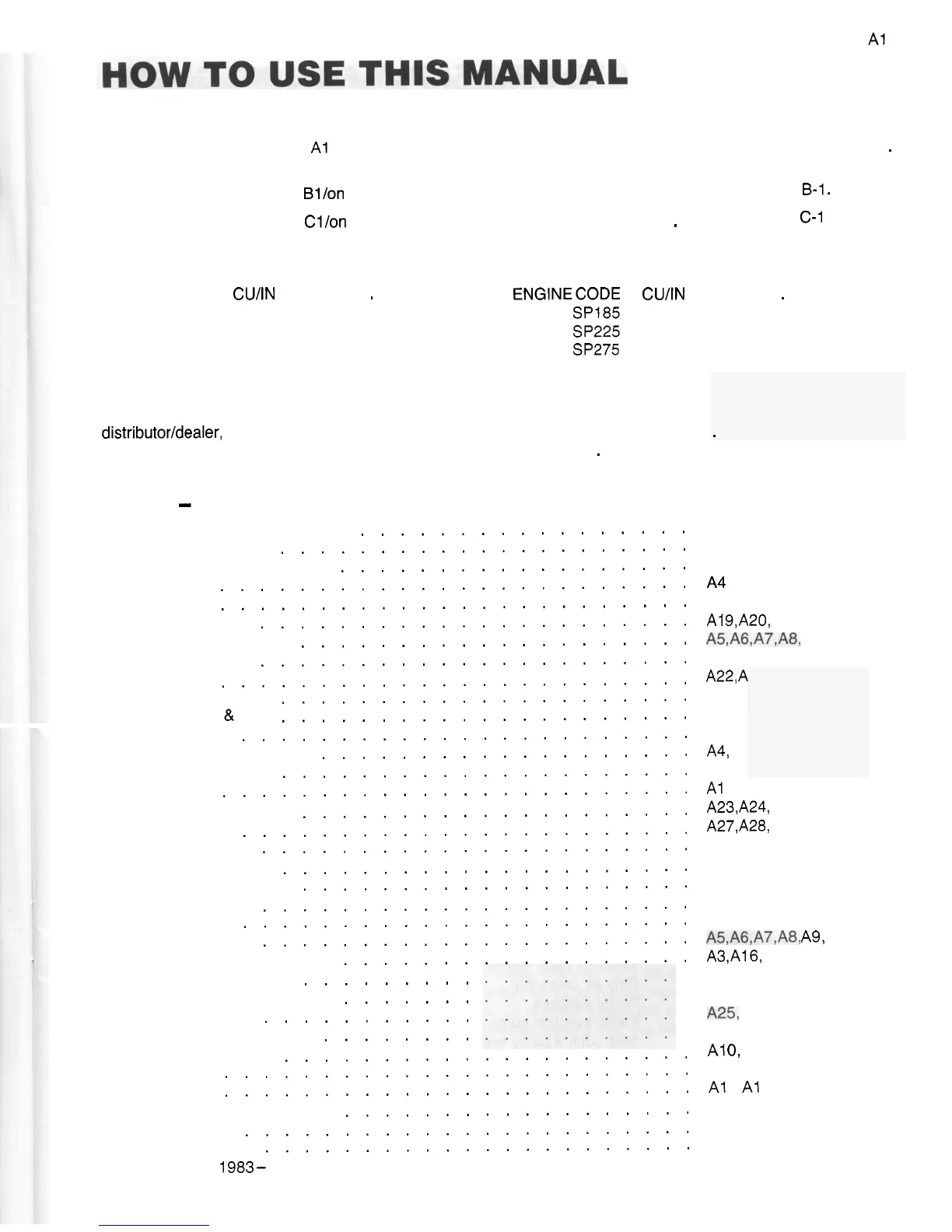
This manual is divided into sections as follows:
SECTION
A
.
Pages Nos
.
A1
/on
.
General data. specifications. installations. adjustments. maintenance. etc
.
SECTION B
-
Page Nos . Bl/on
-
Parts identification of Ford base engines . See index on page
B-1
.
SECTION C
-
Page Nos . Cllon
-
Parts identification of Lehman Marine parts
.
See index page
C-1
.
See index below .
In order to provide a simple method of identification. all models included herein have been assigned a “code”. letter
as follows:
-
ENGINE CODE CUIIN NO . CYLS
.
YEARS ENGINECODE CUIIN NO . CYLS
.
YEARS
M
-
Super
90 254 4 6/82
-
S
-
Super
SP185 363 6 6/82
-
N
-
Super
135 380 6 6/82
-
P
-
Super
SP225 363 6 6/82
-
T
-
Super
SP275 363 6 6/82
-
Instructions for Ordering Parts
Parts listed in this manual may be ordered through any Lehman distributor or dealer or. in areas not served by a
distributorldealer. direct from the Lehman companies . Prices will be quoted upon request
.
In order to prevent errors.
please order any required items by exact part number and name of part
.
When ordering parts. please advise model
number and serial number of the engine
.
Index
-
Section
A
Air bleeding the fuel system
Before operation
.....................
Bleeding the fuel system
..................
Break
-
in
........................
Controls
........................
Cooling system
......................
Dimensions. engine
....................
Draining engine
......................
Electrics
........................
Fault
-
finding guide
.....................
Filters. fuel
&
air
.....................
Fuel system
.......................
Identification of models
...................
Idling adjustment
.....................
Lift pump
........................
Lubrication system
....................
Maintenance
.......................
Minor repairs
......................
Nameplate data
.....................
Oil recommendations
....................
Power charts
......................
Running
-
in
.......................
Specifications
......................
Starting. stopping engine
..................
.................
Tachometer take
-
off
.........
Timing the injection pump
.......
Transmission
...........
Trouble
-
shooting chart
........
Valve adjustments
.....................
Vee belt
........................
Water heater connection‘
..................
Winterizing
.......................
(copyright
1983-
LEHMAN POWER CORPORATION Newark. Delaware)
Warranty
........................
Wiring diagram
......................
23
27
18. A19
4
A18
A3
A18
A4
A16
A1 9.A20. A21
A5.A6.A7.A8. A9
A21
.
A29
A22.
A
A15
A1A 9.
A1A 7.
144. A1
A29
A1 8. A19
A23.A24. A25
A27.A28. A29
A27. A28
A4
A24
.
A2 5
A5
.
A6
.
A7
.
A8
.
A9
A4
A5.A6.A7.A8. A9.
A10
A3.Al6. A17
A22
A19
1425. A26
A15
A1
0.
A27
A28
A1
1
.
A1 2. A13
A30
A21
.
A29
A23