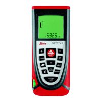
This document outlines the setup, calibration, and use of an electronic measurement system for horizontal jumps, specifically focusing on the Leica Disto A5 unit. The system is designed to provide precise measurements in events like the long jump and triple jump, enhancing accuracy and efficiency compared to traditional steel tape methods.
Function Description
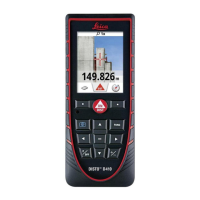
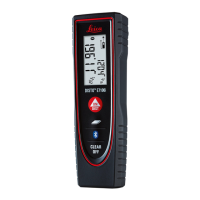
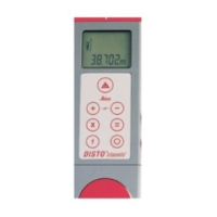
The core function of this device is to electronically measure the distance of horizontal jumps. It consists of a beam, a spotting laser, and a measurement device (e.g., Leica Disto A5). The beam acts as a guide rail, positioned parallel to the landing area, typically 24" to 30" from its nearest edge. The spotting laser, mounted on a trolley that slides along the beam, is used to pinpoint the exact landing mark in the sand. The measurement device, securely attached to the beam, then calculates the distance from a fixed reference point (the scratch line of the take-off board) to the laser's spot. This setup ensures that the measurement is taken perpendicular to the scratch line, which is crucial for accurate results in track and field. The system aims to measure any legal attempt where the athlete makes the landing area, eliminating the need for alternative measurement methods for shorter jumps if the laser can reach the leading edge of the pit.
Usage Features
The usage of this electronic measurement system involves several key steps:
-
Basic Setup of the Beam:
- A certified steel tape is used to establish a baseline. The "0" end of the tape is placed at the scratch line of the take-off board and extended into the pit, perpendicular to the scratch line (using the lane boundary line as a guide). This tape helps in initial alignment and calibration.
- The beam, which holds both the spotting laser and the reading device, is then set up. The reading device is attached securely near the end of the beam closest to the take-off board.
- The spotting laser is attached to a trolley that moves along the beam. Lubricant should be applied to the beam to ensure the trolley slides easily.
- The beam should be level both in the direction of and perpendicular to the landing area. Shims or built-in leveling mechanisms may be used, and sandbags or other stable weights might be needed to prevent shifting.
- The beam should be positioned a minimum of 24" to 30" from the nearest edge of the landing area.
-
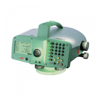
Calibration of the Measurement Device (Leica Disto A5):
- Power On: Turn the unit on by pressing the "On/Dist" key.
- Access Offset Menu: Press the "Menu" button repeatedly until "Offset" appears on the screen.
- Reset Offset to Zero: Press the "=" key to display the current offset. Use the "+" and "–" keys to set the offset to 0.000m. Confirm by pressing the "=" key.
- Initial Measurement for Offset Calculation: With the spotting laser aligned with a known check mark (e.g., 4.50m on the steel tape), press the "On/Dist" key. The device will display the measurement from its end to the laser. For instance, if the marker rod is at 4.50m and the device reads 3.500m, an offset of 1.000m is needed.
- Set New Offset: Repeat the process of accessing the "Offset" menu. Use the "+" and "–" keys to set the offset to the calculated value (e.g., 1.000m). Confirm by pressing the "=" key.
- Verify Calibration: Without moving the spotting laser, press the "On/Dist" key again. The screen should now display approximately the correct distance (e.g., 4.500m). The last digit to the right is ignored for official readings (e.g., 4.508m is read as 4.50m).
- Second Checkmark: Move the spotting laser to a second checkmark and verify the distance.
- In-Event Checkmark: Establish an in-event checkmark by placing a small, undisturbed marker outside the landing area. Record this distance. This allows for quick verification of beam stability between flights or trials.
-
Measuring the Landing Mark:
- Stake Placement: After the athlete exits the pit, insert a stake into the sand. The middle of the white tape on the stake must be inside the depression made by the jumper, not in front of it, and the tape must face the guide rail.
- Laser Alignment: Slide the scope carriage along the rail until the spotting scope beam aligns with the edge of the white line on the stake nearest the take-off board. Step back from the rail.
- Take Measurement: Press the "On/Dist" button to turn on the laser. The screen will display three hashes, indicating the laser is ready. Press "On/Dist" again to take the measurement.
- Reset for Next Measurement: Press "On/Dist" again to reset the laser while keeping the previous measurement on screen.
- Multiple Measurements: If continuous measurements are taken without pressing "Clear/Off," the device will display the previous three measurements.
Maintenance Features
Proper maintenance ensures the longevity and accuracy of the electronic measurement system:
- Protection from Elements: Keep a couple of towels available to cover the spotting laser and the measuring device between rounds, especially in wet or sunny conditions, to protect them from environmental damage.
- Lubrication: Apply a suitable lubricant (e.g., silicon or WD-40) to the beam to ensure the trolley slides smoothly. The type of lubricant may depend on the beam's material.
- Cleaning: Periodically wipe down the beam to remove accumulated sand and grit, which can impede the trolley's movement and potentially damage the system.
- Laser Type: Note that green lasers generally work best for outdoor competition, while red lasers are more suitable for indoor use, indicating a need for consideration based on the environment.
- Leveling: Regularly check the level of the beam using a small torpedo level. Have wood shims on hand for any necessary adjustments to maintain a level surface.
- Documentation: Keep a tablet or small notebook to record setup measurements and checkmark measurements. This helps in verifying the system's consistency and detecting any shifts.
- Steel Tape: Ensure a steel tape of appropriate length (at least 25' for long jump, 50' for triple jump) is available. These are typically part of the horizontal events crew bag and are essential for initial setup and verification.
- Post-Competition Verification: After the competition, repeat the initial setup process by running the steel tape parallel to the lane boundary and measuring the same points. The measurements should match those taken during the initial setup, confirming the system's stability throughout the event.