EasyManuals Logo

Leica GS14 User Manual

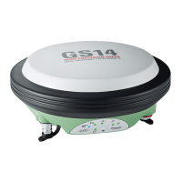
Leica GS14
58 pages
To Next Page IconTo Next Page
To Previous Page IconTo Previous Page
Page #56 background imageLoading...
Page #56 background image
GS14/GS16, Pin Assignments and Sockets
56
Appendix A Pin Assignments and Sockets
Description Some applications require knowledge of the pin assignments for the instrument ports.
In this chapter, the pin assignments and sockets for the instrument ports are
explained.
Ports at the
instrument
underside
Pin assignments for
port P1
a) QN-connector, only for models with
UHF radio
b) Port 1 (USB and serial)
004118_002
a
b
1
7
6
8
5
4
3
2
PIN_001
Pin Signal Name Function Direction
1 USB_D+ USB data line In or out
2 USB_D- USB data line In or out
3GND Signal ground -
4 RxD RS232, receive data In
5 TxD RS232, transmit data Out
6 ID Identification pin In or out
7 PWR Power input, 10.5V-28V In
8 GPIO RS232, general-purpose signal In or out

Other manuals for Leica GS14

Questions and Answers:

Question and Answer IconNeed help?

Do you have a question about the Leica GS14 and is the answer not in the manual?

Leica GS14 Specifications

General IconGeneral
GPSL1, L2, L2C, L5
GLONASSL1, L2
GalileoE1, E5a, E5b
BeiDouB1, B2
SBASWAAS, EGNOS, MSAS, GAGAN
QZSSL1, L2C, L5
RTK Initialization Time< 10 seconds
Data Logging RateUp to 20 Hz
PowerRechargeable Li-Ion battery
External Power9-18 V DC
Operating Temperature-40°C to +65°C
Ingress ProtectionIP68
RTK AccuracyH: 8 mm + 1 ppm, V: 15 mm + 1 ppm
Static AccuracyHorizontal: 3 mm + 0.5 ppm, Vertical: 5 mm + 0.5 ppm
CommunicationBluetooth, USB

Related product manuals