Do you have a question about the LEM Avalon AV12-4 and is the answer not in the manual?
Overview of technical specifications for all models.
Lists of spare parts for passive and active versions.
Schematic block diagrams for various speaker models.
Detailed procedures for testing and adjusting amplified speakers.
Warning about qualified personnel and warranty.
Precautions for handling sensitive electronic components.
Sales division address and online presence.
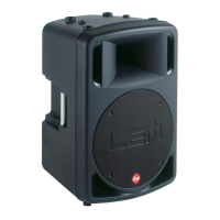
Detailed specs for AV12, AV15, AV15S models.
Specs for active versions AV12-4, AV12-8, AV15-4, AV15-8, AV155.
Schematics for 768202 to 768206 crossover boards.
Pin configurations for common transistor packages used.
List of parts for AV-12 4 Ohm passive model.
List of parts for AV-15S 4 Ohm passive model.
List of parts for AV-12 8 Ohm passive model.
List of parts for AV-15 4 Ohm passive model.
List of parts for AV-15 8 Ohm passive model.
Block diagram for AV15SA amplified subwoofer.
Block diagram for AV15A amplified loudspeaker.
Block diagram for AV12A amplified loudspeaker.
Safety precautions before starting any test.
Important notes and advice for maintenance.
Steps for visually checking the unit before operation.
List of necessary tools and equipment for testing.
Technical specifications specific to the AV12A model.
Initial setup steps before testing AV12A.
Procedure for checking power supply voltages on AV12A.
Testing and adjustment for AV12A audio channels.
How to adjust the gain for the AV12A model.
Procedure for setting the bias on the AV12A.
Verifying the frequency response of the AV12A.
Testing the offset detection circuit for AV12A.
Measuring the signal-to-noise ratio for AV12A.
Technical specifications specific to the AV15A model.
Initial setup steps before testing AV15A.
Procedure for checking power supply voltages on AV15A.
Testing and adjustment for AV15A audio channels.
How to adjust the gain for the AV15A model.
Procedure for setting the bias on the AV15A.
Verifying the frequency response of the AV15A.
Testing the offset detection circuit for AV15A.
Measuring the signal-to-noise ratio for AV15A.
Technical specifications specific to the AV15SA model.
Initial setup steps before testing AV15SA.
Procedure for checking power supply voltages on AV15SA.
Testing and adjustment for AV15SA audio channels.
How to adjust the gain for the AV15SA model.
Procedure for setting the bias on the AV15SA.
Verifying the frequency response of the AV15SA.
Testing the offset detection circuit for AV15SA.
Measuring the signal-to-noise ratio for AV15SA.
Further checks on AV15SA power supply.
Further checks on AV15SA audio channels.
Further gain adjustments for AV15SA.
Further bias adjustments for AV15SA.
Further bandwidth checks for AV15SA.
Further offset sensor checks for AV15SA.
Further S/N ratio checks for AV15SA.
General advice for troubleshooting and testing.
Circuit diagram for the 768207 inputs board.
Circuit diagram for the 768211 supply board.
Circuit diagram for the 768202 crossover board.
Circuit diagram for the 768208 inputs board.
Circuit diagram for the 768212 supply board.
Circuit diagram for the 727607 350W amplifier board.
Circuit diagram for the 768204 crossover board.
Circuit diagram for 768210 controls and crossover board.
Circuit diagram for the 768209 inputs board.
Circuit diagram for the 768213 supply board.
Circuit diagram for the 727607 350W amplifier board.
List of parts for AV-12A active model.
List of parts for AV-15A active model.
List of parts for AV-15SA active model.
| Type | Passive Speaker |
|---|---|
| Configuration | 2-way |
| LF Driver Size | 12" |
| Impedance | 8 Ohms |
| Tweeter Size | 1.4 inches |
| Inputs | Speakon |
| HF Driver Size | 1.4 inches |