Do you have a question about the LEM K Series and is the answer not in the manual?
Highlights essential warnings about electric shock, unauthorized opening, and user-serviceable parts.
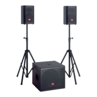
Introduction to the K 3 Active speaker system.
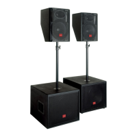
Introduction to the K 6 Active speaker system.
Instructions for connecting the enclosure to the mains power supply.
Procedure for safely switching the equipment on and off.
Guidelines for proper handling of connectors and controls.
Advice on avoiding interference and managing earth loops.
Guidance on using correct signal cables and cable care.
Recommendations for protecting the enclosure and avoiding damage.
Instructions on what to do in case of equipment malfunction.
Advice on keeping the manual and original packaging.
Diagrams showing the physical layout and dimensions of the K 3 Active.
Diagrams showing the physical layout and dimensions of the K 6 Active.
Description of the balanced COMBO connector for line signal input.
Description of the balanced XLR-M connector for signal output.
Explanation of the volume control function.
Explanation of the SIGN/LIMIT indicator LED.
Explanation of the SHIELD selector control.
Explanation of the LIMIT control for bypassing the limiter.
Description of the ON/OFF power switch.
Description of the main power socket.