9
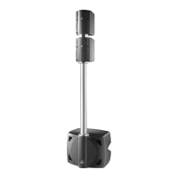
SPX SUB ACTIVE connection panel
SIGN/CLIP
Indicator LED: this is a two-tone LED (green/red) able to show 3 different conditions:
a) off: no signal
b) green/SIGNAL: external signal present (minimum level: -26dB)
c) red/COMPRESSOR: internal compressor operating. It indicates when the compressor starts operating
following the detection of an excessively high signal level being fed out by the system amplifiers. In this
case, the compressor lowers the signal level to avoid damage to the enclosure components and
amplifier clipping. The compressor threshold and time values have been carefully studied and assessed
in order to keep the signal within safety levels and avoid reduced dynamics.
X-OVER
Control for selecting the frequency of the SPX SUB built-in crossover. SPX SUB has a built-in 12dB/
oct. electronic crossover with variable frequency, which separates the signal sent to the internal amplifier
(low frequencies) from the signal sent to the satellites (mid-high frequencies). This selector enables to
choose the crossover frequency in a continuous range of values from a minimum of 80Hz to a maximum
of 320Hz. This function can be extremely useful, as the ideal crossover frequency can often vary
considerably according to the type of satellite used, the type of signal to be reproduced or the environment
in which the system is used. We therefore suggest that a series of tests be carried out when the system
is installed and a decision taken according to requirements and personal taste.
OUTPUT
XLR-M + JACK connectors: SPX SUB has two balanced LEFT & RIGHT outputs with double connector,
to enable the use of the system in STEREO or MONO.
The following are the connections to carry out for these setups.
• STEREO configuration (see ➪ Connection examples):
RIGHT CHANNEL ➪ connect the mixer’s RIGHT output to the sub-woofer’s RIGHT input and the sub-
woofer’s RIGHT output to the RIGHT input of the powered enclosure;
LEFT CHANNEL ➪ connect the mixer’s LEFT output to the sub-woofer’s LEFT input and the sub-woofer’s
LEFT output to the LEFT input of the powered enclosure.
MONO configuration (see ➪ Connection example):
RIGHT CHANNEL ➪ connect the mixer’s RIGHT output to one of the two inputs (LEFT or RIGHT) of the
RIGHT-HAND sub-woofer and the corresponding sub-woofer output to the input of the RIGHT-HAND
amplified enclosure or the RIGHT-HAND channel of the power amplifier;
LEFT CHANNEL ➪ connect the mixer’s LEFT output to one of the two inputs (LEFT or RIGHT) of the
LEFT-HAND sub-woofer and the corresponding sub-woofer output to the input of the LEFT-HAND amplified
enclosure or the LEFT-HAND channel of the power amplifier.
SHIELD
Control for separating the electrical earth from that of the chassis: under certain conditions, this
selector can enable to break earth loops which can form when several units are connected together and
often cause hum or other annoying noises.
POWER
ON/OFF switch with indication LED.
A.C. ~
Mains power socket: connect the mains cable supplied with the unit to this socket.