2 460989001B
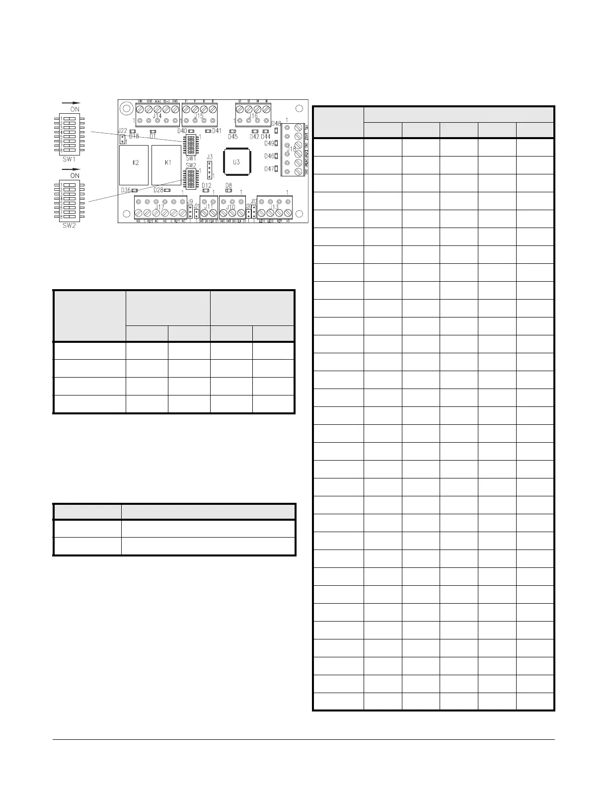
Setting DIP Switches
SDC dip switches
Communication Baud Rate (SW1)
Configure the baud rate using SW1 switches 1-4. (Switch 5 is used for LED
control. Switches 6-8 are not used.)
Note: If you are not using OSDP readers, SW1 switch 3 & 4 do not
need to be set as indicated here.
LED Mode
SW1 switch 5 is used for LED control. It is read at boot time. If you make a
change to this setting, be sure to restart.
Device Address (SW2)
Configure the board address using SW2. (Switches 6-8 are not used.)
Baud rate SW1 switch for
host
SW1 switch for
OSDP readers
(Aux ports)
1: 2: 3: 4:
2400 bps off off off off
9600 bps ON off ON off
19200 bps off ON off ON
38400 bps ON ON ON ON
SW1 Switch 5 State
ON LEDs behave as the Access (LNL) series module.
off LED behavior is in Normal Mode
Address SW2 switch
5: 4: 3: 2: 1:
0 off off off off off
1 off off off off ON
2 off off off ON off
3 off off off ON ON
4 off off ON off off
5 off off ON off ON
6 off off ONONoff
7 off off ONONON
8 off ON off off off
9 off ON off off ON
10 off ON off ON off
11 off ON off ON ON
12 off ON ON off off
13 off ON ON off ON
14 off ONONONoff
15 off ONONONON
16 ON off off off off
17 ON off off off ON
18 ON off off ON off
19 ON off off ON ON
20 ON off ON off off
21 ON off ON off ON
22 ON off ON ON off
23 ON off ON ON ON
24 ON ON off off off
25 ON ON off off ON
26 ON ON off ON off
27 ON ON off ON ON
28 ON ON ON off off
29 ON ON ON off ON
30 ON ON ON ON off
31 ON ON ON ON ON