Do you have a question about the LenelS2 LNL-X2210 and is the answer not in the manual?
Details on how the controller communicates with the host via Ethernet.
Describes supported signaling types and device counts for Reader Port 1.
Describes supported signaling types, contact relays, and inputs for Reader Port 2.
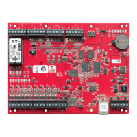
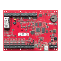
Detailed pinout and function for TB1 through TB5 terminal blocks.
Description of jumper settings and physical ports like USB, Ethernet, and microSD.
Defines the operational modes based on DIP switch settings.
Lists the default network settings for the controller.
Procedure to erase configuration and reset the device to defaults.
Details on powering the LNL-X2210 via Ethernet or local 12 VDC.
Specifies the on-board Ethernet port for host communication.
Details on reader signaling types, power, and multi-drop device support.
Illustrations showing typical reader connections for different protocols.
Wiring for multiple remote serial I/O devices using MSP1 protocol.
Wiring for OSDP protocol devices on Reader Port 1.
Explanation of input circuit configurations and resistor requirements.
Details on Form-C relay connections for door locks and alarms.
Guidance on selecting diodes to protect relay circuits from EMF feedback.
Information on the SRAM backup battery and data retention.
Recommendations for securing the controller during installation and operation.
Explanation of LED behavior during power-up and initialization.
Defines the meaning of LEDs after the controller has initialized.
Detailed electrical, mechanical, and environmental specifications of the device.
UL 294 performance levels for Standby Power, Endurance, Line Security, and Destructive Attack.
Guidelines for UL listed installations, particularly regarding power sources.
How to view and manage the controller's firmware version.
Information on optional mounting accessories like covers and junction boxes.
FCC rules and conditions for device operation.
Limitations on product use, liability, and warranty information.
| Model | LNL-X2210 |
|---|---|
| Operating Voltage | 12 to 24 VDC |
| Reader Ports | 2 |
| Max Readers | 2 |
| Inputs | 4 |
| Max Inputs | 4 |
| Max Outputs | 4 |
| Transaction Storage | 50, 000 |
| Outputs | 4 |
| Communication | RS-485, Ethernet |
| Memory | 8 MB Flash |
| Cardholder Capacity | 500, 000 |
| Operating Temperature | 70°C |
| Humidity | 5% to 95% non-condensing |
| Dimensions | 1.0 in. |