EasyManua.ls Logo

LenelS2 LNL-X4420 - User Manual

LenelS2 LNL-X4420
11 pages
Print Icon
To Next Page IconTo Next Page
Loading...
For detailed information, refer to the hardware documentation for the host
application.
© 2021 Carrier. All Rights Reserved. LenelS2 is a part of Carrier. 1 QR50L-1039E 4.004
Intelligent Controller LNL-X4420 with Two Reader
Interfaces Quick Reference
General
The LNL-X4420 intelligent controller provides decision making, event reporting, and database storage for the Lenel
hardware platform. Two reader interfaces provide control for two doors.
The LNL-X4420 communicates with the host via on-board 10Base T/100Base-TX Ethernet port or the Micro USB
port (2.0) with an optional Micro USB to Ethernet adapter.
Two physical barriers can be controlled with the LNL-X4420. Each reader port can accommodate a read-head that
utilizes TTL (D1/D0, Clock/Data), F/2F or 2-wire RS-485 electrical signaling (OSDP reader for example) and also
provides tri-state LED control and buzzer control (one wire LED mode only). Four Form-C relay outputs may be
used for door strike control or alarm signaling. Eight inputs are provided for monitoring the door contacts, exit push
buttons, and alarm contacts. Input circuits can be configured as unsupervised or supervised. The LNL-X4420 requires
12 to 24 VDC for power.
LNL-X4420 Hardware
3.00 [76.20]
8.00 [203.20]
0.50 [12.70]
0.25 [6.35]
2.00 [50.80]
6.00 [152.40]
Ø.156 [Ø3.96}
8 places
2.00 [50.80]
NO
C
NC
NO
C
NC
OUT1
OUT2
C
NC
NO
C
NC
OUT3
OUT4
NO
TB10
TB11
DAT
D0
CLK
D1
BZR
LED
VO
TB8
GND
DAT
D0
CLK
D1
BZR
LED
VO
TB9
GND
READER 1 READER 2
TR+
TR-
GND
TB2
TR+
TR-
GND
TB3
IN3
IN4
TB4
IN1
IN2
TB5
TB6
IN5
IN6
TB7
IN7
IN8
TB1
GND
FLT
GND
VIN
GND
TMP
RESET
S2
BT1
3V BR/CR2330
^
|
1
S1
ON
2
3
4
J6
J2
J8
J9
J5
IN1
IN2
IN3
IN4
IN5
IN6
IN7
IN8
K
1
K
2
K
3
K
4
Output status LEDs Input status LEDs
J7
PASS 12V
1
2
3
4
5
R1
R2
D16
Battery: BR/CR2330
(replace annually)
S2: Reset switch
S1: DIP
switches
Status
LEDs
J2: Ethernet
jack
Earth
ground
J6: Micro USB
jack
J8: microSD
card
J7: Reader
voltage
select
5.50 [139.70]
J19
J19: Battery backup
+
1
3
2
4
J10
-
J10: Remote
status LED
connection
Question and Answer IconNeed help?

Do you have a question about the LenelS2 LNL-X4420 and is the answer not in the manual?

Summary

General

LNL-X4420 Hardware Overview

LNL-X4420 Wiring

Jumpers and Jacks Configuration

DIP Switches

Factory Default Communication Parameters

Bulk Erase Configuration Memory

Bulk Erase Steps

Input Power and Wiring

Communication Wiring

Reader Wiring

J7 Reader Power Select

Input Circuit Wiring

Relay Circuit Wiring

Diode Selection for Relays

Memory and RTC Backup Battery

IT Security Best Practices

Status LEDs Interpretation

LED Status Indicators Running

Technical Specifications

UL Listed Installations

Regulatory Information and Compliance

Product Warnings and Disclaimers

Overview

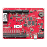
The LenelS2 LNL-X4420 is an intelligent controller designed for access control systems, providing decision-making, event reporting, and database storage for the Lenel hardware platform. It features two reader interfaces, allowing control for two doors.

Function Description:

The LNL-X4420 serves as a central component in an access control system, managing access decisions, logging events, and storing critical data. It communicates with a host system via an on-board 10BaseT/100Base-TX Ethernet port or a Micro USB port (2.0), which can be connected to an optional Micro USB to Ethernet adapter.

Each of the two reader ports supports various reader technologies, including those utilizing TTL (D1/D0, Clock/Data), F/2F, or 2-wire RS-485 electrical signaling (e.g., OSDP readers). The controller also provides tri-state LED control and buzzer control (one-wire LED mode only) for reader feedback.

For door strike control or alarm signaling, the LNL-X4420 offers four Form-C relay outputs. Additionally, it includes eight inputs for monitoring door contacts, exit push buttons, and other alarm contacts. These input circuits can be configured as either unsupervised or supervised, offering flexibility in security monitoring. The device operates on a 12 to 24 VDC power supply.

Important Technical Specifications:

  • Primary Power: 12 to 24 VDC ± 10%, 550 mA maximum (excluding reader and USB ports).
  • Reader Ports Power: 600 mA maximum (adds 600 mA to primary power current). Power to readers is selectable between 12 VDC (if VIN > 20 VDC) or "pass-through" from the input voltage (VIN), with a maximum of 300 mA per reader port.
  • Micro USB Port Power: 5 VDC, 500 mA maximum (adds 270 mA to primary power current).
  • Inputs: Eight unsupervised/supervised inputs (standard EOL: 1k/1k ohm, 1%, ½ watt). Two additional unsupervised inputs dedicated for cabinet tamper and UPS fault monitoring.
  • Outputs: Four Form-C dry contact relays.
    • Normally Open (NO) contact: 5 A @ 30 VDC resistive.
    • Normally Closed (NC) contact: 3 A @ 30 VDC resistive.
  • Reader Interface: TTL compatible, F/2F, or 2-wire RS-485.
  • RS-485 Mode: 9,600 to 115,200 bps, asynchronous, half-duplex, 1 start bit, 8 data bits, 1 stop bit. Maximum cable length: 2000 ft. (609.6 m).
  • LED Output: TTL levels, high>3 V, low<0.5 V, 5 mA source/sink maximum.
  • Buzzer Output: Open collector, 12 VDC open circuit maximum, 40 mA sink maximum.
  • Host Communication: Ethernet (10-BaseT/100Base-TX) and Micro USB port (2.0) with optional pluggable USB2-OTGE100 adapter.
  • Serial I/O Device: Two 2-wire RS-485 ports, 2,400 to 115,200 bps, asynchronous, half-duplex, 1 start bit, 8 data bits, 1 stop bit.
  • Memory and Clock Backup Battery: 3 Volt Lithium, type BR2330 or CR2330.
  • microSD Card: Format: microSD or microSDHC; 2GB to 8GB.
  • Environmental Temperature: Storage: -55 to +85 °C (-67° to 185° F). Operating: 0 to +70 °C (32° to 158° F).
  • Humidity: 5 to 95% RHNC.
  • Dimensions: 8 in. (203.2 mm) W x 6 in. (152.4 mm) L x 1 in. (25 mm) H.
  • Weight: 10.65 oz. (302 g) nominal, board only.
  • UL 294 Performance Levels: Standby Power (I), Endurance (IV), Line Security (I), Destructive Attack (I).

Usage Features:

  • Flexible Reader Support: Accommodates various reader types (TTL, F/2F, 2-wire RS-485 OSDP) and provides LED/buzzer control.
  • Configurable Inputs: Eight general-purpose inputs can be set as unsupervised or supervised for enhanced security monitoring. Supervised circuits require two 1k ohm, 1% resistors for open, closed, open circuit, shorted, grounded, and foreign voltage reporting.
  • Relay Outputs: Four Form-C relays for controlling door strikes or alarm devices. Diode protection is recommended for door lock mechanisms to prevent damage.
  • Communication Options: Ethernet for network connectivity and Micro USB for local connection or with an adapter for additional Ethernet.
  • DIP Switches (S1): Four DIP switches configure the operating mode, including normal operation, enabling default user credentials, using factory/Lenel default communication parameters, and initiating bulk erase prompt mode.
  • Jumpers: Used to configure reader port power (12V or VIN pass-through) and RS-485 End-Of-Line (EOL) termination for ports 1 and 2. Jumper J7 should be set to 12V only if input voltage (VIN) is greater than 20 VDC to prevent damage.
  • Status LEDs: Provide visual feedback on power, host communication, internal/external SIO communication, reader activity, Ethernet status (speed, link), input status, and relay energization.
  • IT Security: Supports secure password creation for web configuration, disabling SNMP, Zeroconf discovery, and the web configuration module itself. Data encryption can be enabled over the host communication port.
  • Bulk Erase Function: Allows for erasing all configuration and cardholder data, updating OEM default parameters, and recovering from database corruption.

Maintenance Features:

  • Battery Replacement: The BR/CR2330 lithium battery for static RAM and real-time clock backup should be replaced annually. Jumper J19 controls battery backup enablement.
  • Reset Switch (S2): Pressing the reset switch reboots the LNL-X4420.
  • Bulk Erase Procedure: A defined sequence using DIP switches S1 and power cycling allows for complete memory erasure, useful for sanitizing the board or recovering from critical errors.
  • LED Diagnostics: Status LEDs provide crucial information during power-up, initialization, and normal operation, aiding in troubleshooting and monitoring device health.
  • Firmware Updates: The device's functionality can be updated, and it can be configured to report and function like an LNL-4420 for compatibility with older host software versions.

LenelS2 LNL-X4420 Specifications

General IconGeneral
BrandLenelS2
ModelLNL-X4420
CategoryController
LanguageEnglish

Related product manuals