506694-01 Issue 1720 Page 1 of 16
Save these instructions for future reference
INSTALLATION INSTRUCTIONS
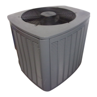
13ACD Split System Air Conditioner
with Dry Nitrogen Holding Charge
215 Metropolitan Drive
West Columbia, SC 29170
This manual must be left with the homeowner for future reference.
This is a safety alert symbol and should never be ignored. When you see this symbol on labels or in
manuals, be alert to the potential for personal injury or death.
Table of Contents
General ........................................................................2
Unit Dimensions - inches (mm) ...................................2
Parts Arrangement.......................................................2
Shipping and Packing List ...........................................3
Torque Requirements ..................................................3
Operating Gauge Set and Service Valves ...................3
Recovering Refrigerant from Existing System ............. 4
New Outdoor Unit Placement ......................................5
Replacement Line Set .................................................6
Brazing Connections ...................................................7
Removing Existing Metering Device and Flushing Line
Set and Indoor Coil ....................................................10
Installing New Indoor Metering Device ...................... 11
Leak Test Line Set and Indoor Coil ............................ 12
Evacuating Line Set, Indoor Coil and Outdoor Unit ... 13
Electrical ....................................................................14
Servicing Outdoor Unit Delivered Void of Nitrogen
Charge .......................................................................15
Maintenance ..............................................................15
This unit is factory-charged with dry nitrogen. The
unit is intended for installation in existing HCFC-22
systems. Carefully follow all installation procedures.
Open both service valves to evacuate system. This
unit is constructed without a factory installed lter drier.
Field-provided liquid line lter drier should be installed
per Figure 6A.
NOTE
Installation or repairs made by unqualied persons can
result in hazards to you and others. Installation MUST
conform with local building codes or, in the absence of
local codes, with the National Electrical Code NFPA
70/ANSI C1-1993 or current edition and Canadian
Electrical Code Part 1 CSA C22.1.
WARNING
Improper selection of a matching indoor unit and
a matching metering device, improper installation,
adjustment, alteration, service or maintenance may void
the warranty. The qualied installer or agency must use
factory-authorized kits or accessories when modifying
this products. Refer to the individual instructions
packaged with the kits or accessories when installing.
CAUTION
These instructions are intended as a general guide and
do not supersede national, state or local codes in any
way.
NOTE
This product contains a chemical known to the State
of California to cause cancer, birth defects or other
reproductive harm.
WARNING