Page 2
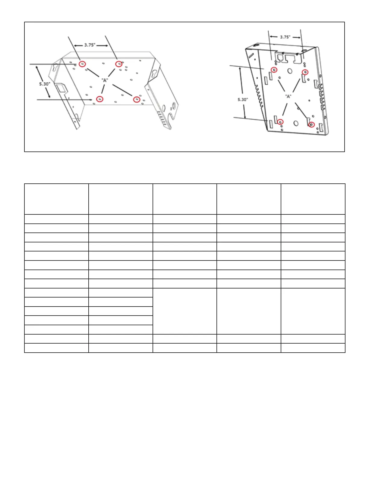
FIGURE 1
TABLE 1
Integrated Ignition Control Markings Cross Reference
Tyep
Connection
10M9301
12L6901
32M8801
56L8401
24L8501
56L8301
63K8901
97L4801
69M0801
Replacement
Control
1/4” QC COOL-H ABC COOL COOL COOL
1/4” QC HEAT-H ACH HEAT HEAT HEAT
1/4” QC N/A ACB LOW N/A CONT
1/4” QC PARK(2) PARK(2) PARK(2) PARK (3)
1/4” QC LINE-H 120 HOT LINE L1
1/4” QC XFMR-H VAC TX XFMR XFMR
1/4” QC EAC-H ACC EAC EAC
1/4” QC HUM-H HTG ACC HUM HUM
1/4” QC LINE-H
NEUTRAL 120 VAC
(5)
NEUTRAL 120 VAC
(5)
NEUTRAL (5)
1/4” QC HUM--N
1/4” QC EAC-N
1/4” QC XFMR-N
1/4” QC CIR-N
3/16” QC F;AME SENSE FLAME SENSE FS N/A*
Plug 12-PIN 9-PIN 12-PIN 12-PIN
* Flame sense signal is routed to pin 2 of 12 pin connector on replacement control.
8 - Remove the existing hot surface ignitor and its
mounting bracket from the burner assembly. Install
the replacement ignitor and appropriate new
mounting bracket per Figure 3.
NOTE - The red foam gasket included with the
replacement ignitor is not needed.
9 - Connect the enclosed 2-pin ignitor harness adapter
between the new ignitor and existing furnace
connector.
10 - Replace the access panel.
11 - Restore the electrical power and gas supply.
Referto the furnace installation instructions for
start-up andcheck-out procedures. See table 4 for
diagnosticcodes.