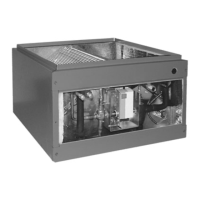
Page 15
EDA INSTALLATION/ SERVICE INSTRUCTIONS
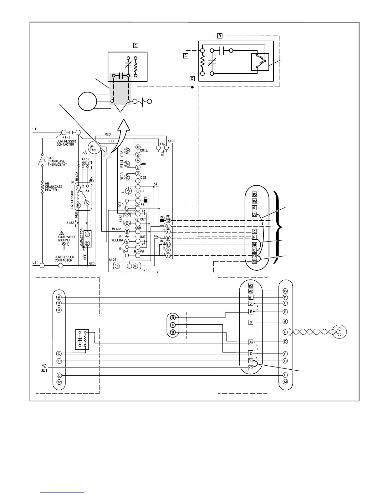
Typical EDA/Heat Pump Wiring Diagram
Figure 13
B4
FAN
Blue
Yellow
Black
K1
1st, cut
yellow wire
here.
Use Wirenuts
*OUTDOOR RELAY
NOT REQUIRED WITH SINGLE-
SPEED OUTDOOR FAN
EDA
Violet
Orange
Purple
Black
Black
Purple
VALVE
ACTUATOR
Yellow
Yellow
2
2nd, rewire
yellow wire
as shown
75
1
3
5
BLACK
PURPLE
BLACK
RED
OUTDOOR
WIRING
(VSM
APPLICATION
ONLY)
Y1Y2 JUMPER − IN FOR
SINGLE− STAGE COOLING;
REMOVED FOR 2−STAGE
COOLING
INDOOR
UNIT
BLUE
BROWN
DSY1 JUMPER − MUST BE
REMOVED FOR HUMIDITROL
OPERATION
SEE CONTROL WIRING BELOW
FOR THERMOSTAT
WONNECTIONS
RO JUMPER − MUST BE
REMOVED FOR HEAT PUMP
APPLICATION
Y1Y2 JUMPER − ONLY
REMOVE IF 2−STAGE COOLING
BLUE
YELLOW
BLUE (NOT REQUIRED FOR SINGLE STAGE)
BROWN (NOT REQUIRED FOR APPLICATIONS WITHOUT LSOM)
RED
BLACK
PURPLE
SignatureStatt
THERMOSTAT
INDOOR
UNIT
OUTDOOR
UNIT
EDA
UNIT
TWISTED PAIR
PURPLE
OUTDOOR
SENSOR
(46M98)
BLACK
Control Wiring
BLUE
RED
FAN RELAY (NOT REQUIRED
WITH SINGLE-SPEED
OUTDOOR FAN)