507266-05 Page 53 of 58Issue 1933
Turning O Gas to Unit
1. Set the thermostat to the lowest setting.
2. Turn o all electrical power to the unit if service is to
be performed.
3. Remove the upper access panel.
4. Move gas valve switch to OFF.
5. Replace the upper access panel.
Failure to Operate
If the unit fails to operate, check the following:
1. Is the thermostat calling for heat?
2. Are access panels securely in place?
3. Is the main disconnect switch closed?
4. Is there a blown fuse or tripped breaker?
5. Is the lter dirty or plugged? Dirty or plugged lters will
cause the limit control to shut the unit o.
6. Is gas turned on at the meter?
7. Is the manual main shut–o valve open?
8. Is the internal manual shut–o valve open?
9. Is the unit ignition system in lockout? If the unit locks
out again, inspect the unit for blockages.
Heating Sequence of Operation
1. When thermostat calls for heat, combustion air inducer
starts.
2. Combustion air pressure switch proves blower
operation. Switch is factory set and requires no
adjustment.
3. After a 15 second pre-purge, the hot surface ignitor
energizes.
4. After a 20 second ignitor warm-up period, the gas
valve solenoid opens.
5. Gas is ignited, ame sensor proves the ame, and the
combustion process continues.
6. If ame is not detected after rst ignition trial, the
ignition control will repeat steps 3 and 4 four more
times before locking out the gas valve. The ignition
control will then automatically repeat steps 1 through
6 after 60 minutes. To interrupt the 60 minute period,
move thermostat from “Heat” to “OFF” then back to
“Heat”. Heating sequence then restarts at step 1.
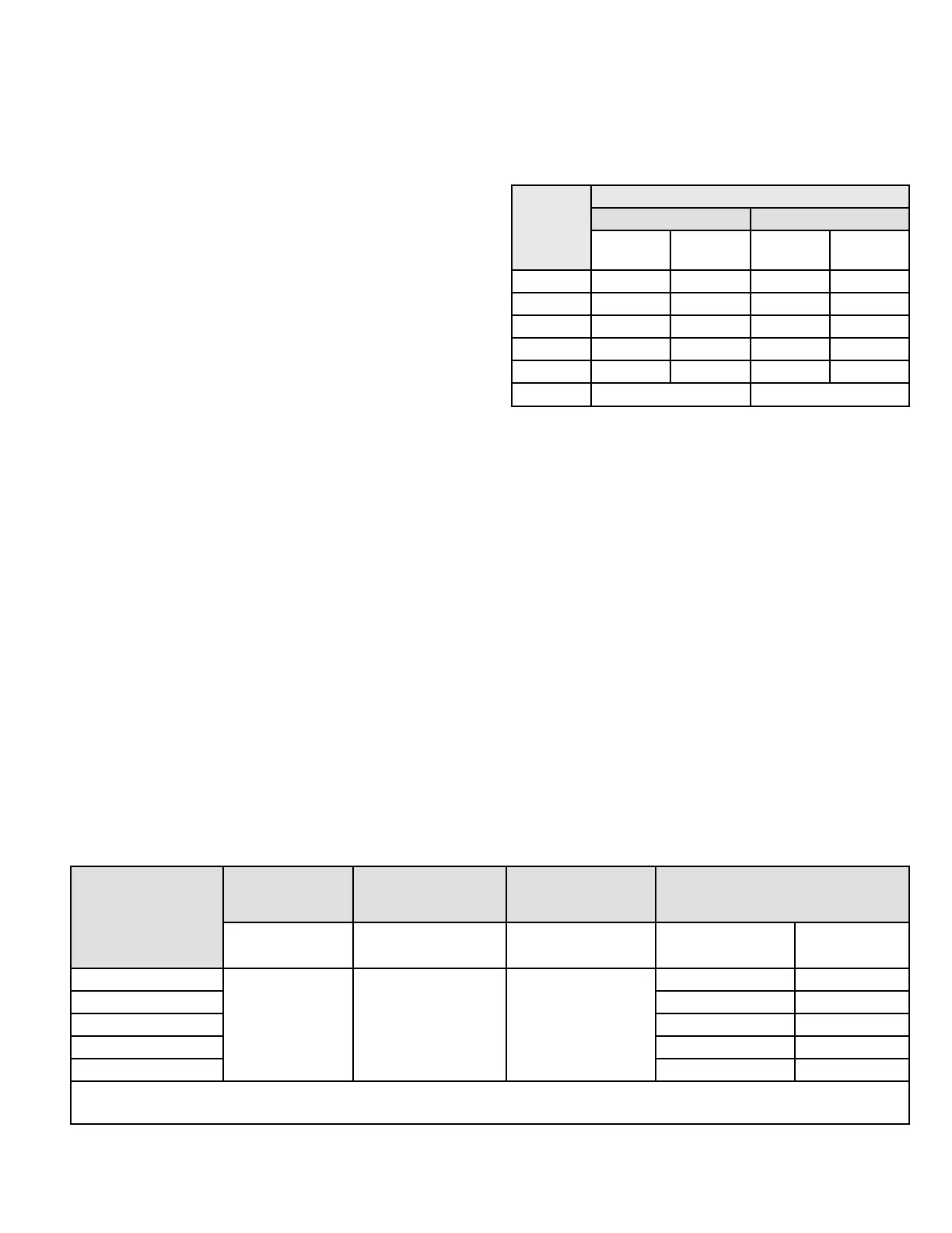
Gas Pressure Adjustment
Gas Flow (Approximate)
Capacity
Seconds for One Revolution
Natural LP
1 cu ft
Dial
2 cu ft
Dial
1 cu ft
Dial
2 cu ft
Dial
-045 80 160 200 400
-70 55 110 136 272
-90 41 82 102 204
-110 33 66 82 164
-135 27 54 68 136
Natural - 1000 btu/cu ft LP - 2500 btu/cu ft
Table 15. Gas Meter Clocking Chart
Furnace should operate at least 5 minutes before checking
gas ow. Determine time in seconds for two revolutions of
gas through the meter. (Two revolutions assures a more
accurate time.) Divide by two and compare to time in Table
15. If manifold pressure matches Table 14 and rate is
incorrect, check gas orices for proper size and restriction.
Remove temporary gas meter if installed.
NOTE: To obtain accurate reading, shut o all other gas
appliances connected to meter.
Supply Pressure Measurement
An inlet pressure post on the inlet side of the gas valve
provides access to the supply pressure. See Figure 74.
Back out the 3/32 Hex screw one turn, connect a piece
of 5/16” tubing and connect to a manometer to measure
supply pressure.
NOTE: Shut unit o and remove manometer as soon as
an accurate reading has been obtained. Take care to re-
tighten the 3/32 Hex screw.
Capacity
Natural to LP/
Propane
High Altitude Natural
Burner Orice Kit
High Altitude LP/
Propane Burner
Orice Kit
High Altitude Pressure Switch
0 - 7500 ft
(0 - 2286m)
7501 - 10000 ft
(2286 - 3048m)
7501 - 10000 ft
(2286 - 3048m)
4501 - 7500 ft
(1371 - 2286m)
7501 - 10000 ft
(2286 - 3048m)
045
11K48 *51W01 11K47
14A47 14A50
070 14A54 14A53
090 14A57 14A54
110 14A46 14A51
135 14A49 14A51
*Conversion requires installation of a gas valve manifold spring which is provided with the gas conversion kit.
Pressure switch is factory set. No adjustment necessary. All models use the factory-installed pressure switch from 0-4500 feet (0-1371 m).
Table 16. Conversion Kit Fan Pressure Switch Requirements at Varying Altitudes
 Loading...