507266-05 Page 9 of 58Issue 1933
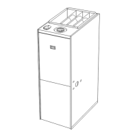
Figure 8. Equipment in Conned Space - All Air from
Outside
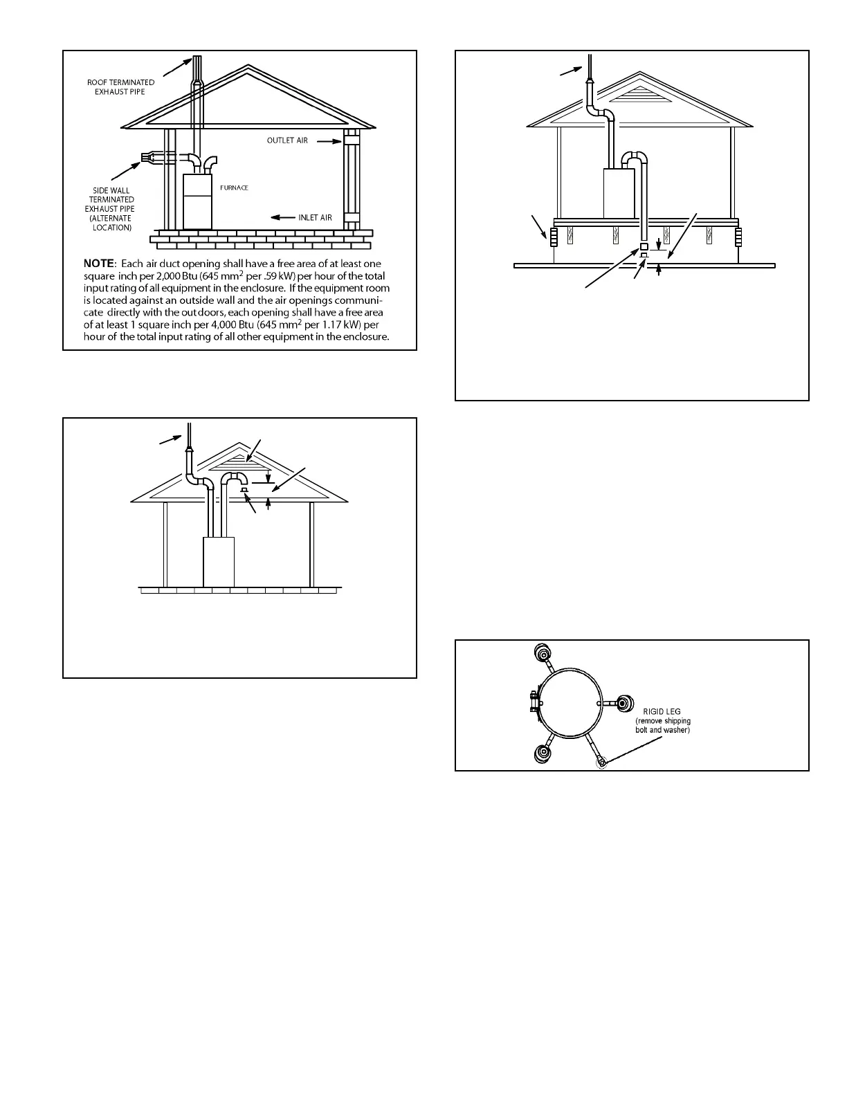
Figure 9. Equipment in Conned Space
(Inlet Air from Ventilated Attic and Outlet Air to
Outside)
Ventilation Louvers
Inlet Air
(Minimum 12 in.
(305mm) above
Attic Floor)
Roof Terminated
Exhaust Pipe
Furnace
*Intake Debris
Screen
(Provided)
* See Maximum Vent Lengths table
NOTE-The inlet and outlet air openings shall each have a
free area of at least one square inch per 4,000 Btu (645mm
2
per 1.17kW) per hour of the total input rating of all equipment
in the enclosure.
When ducts are used, they shall be of the same cross-
sectional area as the free area of the openings to which
they connect. The minimum dimension of rectangular
air ducts shall be no less than 3 inches (75 mm). In
calculating free area, the blocking eect of louvers, grilles,
or screens must be considered. If the design and free area
of protective covering is not known for calculating the size
opening required, it may be assumed that wood louvers
will have 20 to 25 percent free area and metal louvers and
grilles will have 60 to 75 percent free area. Louvers and
grilles must be xed in the open position or interlocked
with the equipment so that they are opened automatically
during equipment operation.
Figure 10. Equipment in Conned Space
(Inlet Air from Ventilated Crawlspace and Outlet Air to
Outside)
Roof Terminated
Exhaust Pipe
Furnace
Ventilation
Louvers
(Crawl Space)
*Intake Debris Screen Provided
Inlet Air
Minimum
12 in. (305mm)
above Crawl
Space Floor
Coupling or
3 in. to 2 in.
Transition
(Field Provided)
* See Maximum Vent Lengths table
NOTE-The inlet and outlet air openings shall each have a
free area of at least one square inch per 4,000 Btu (645mm
2
per 1.17kW) per hour of the total input rating of all equipment
in the enclosure.
Shipping Bolt Removal
Units with 1/2 hp blower motor are equipped with three
exible legs and one rigid leg. The rigid leg is equipped
with a shipping bolt and a at white plastic washer (rather
than the rubber mounting grommet used with a exible
mounting leg). See Figure 11. The bolt and washer must
be removed before the furnace is placed into operation.
After the bolt and washer have been removed, the rigid leg
will not touch the blower housing.
Figure 11.
Units with 1/2 HP
Blower Motor
 Loading...