18
Electrical
Box
Thermostat
connection
Thermostat
connection
Nr OF CABLES X SECTION (mm
2
)
Nr OF CABLES X SECTION (mm
2
)
UNIT
MODEL
76D2
64D2
86D2
48D2
POWER SUPPLY
230V THREE-PHASE
UNITS
UNIT
MODEL
48D2
76D2
64D2
86D2
POWER SUPPLY
400V THREE-PHASE
UNITS
Power supply
WITHOUT
electrical heater (*)
Power supply
WITH
electrical heater (*)
Indoor motor fan
electrical connection
Power supply
electrical heater (optional)
Power supply
WITHOUT
electrical heater (*)
Power supply
WITH
electrical heater (*)
Indoor motor fan
electrical connection
Power supply
electrical heater (optional)
3 x 25 + 1 x 16
3 x 50 + 1 x 25
3 x 95 + 1 x 50
3 x 120 + 1 x 70
3 x 70 + 1 x 35
4 x 1,5
4 x 1,5
4 x 1,5
4 x 2,5
4 x 10 + 3 x 1,5
4 x 10 + 3 x 1,5
4 x 10 + 3 x 1,5
4 x 10 + 3 x 1,5
5 x 10
3 x 25 + 2 x 16
3 x 35 + 2 x 16
3 x 25 + 2 x 16
3 x 35 + 2 x 16
3 x 50 + 2 x 25
4 x 1,5
4 x 1,5
4 x 1,5
4 x 2,5
4 x 4 + 3 x 1,5
4 x 4 + 3 x 1,5
4 x 4 + 3 x 1,5
4 x 4 + 3 x 1,5
3 x 50 + 1 x 25
3 x 95 + 1 x 50
3 x 95 + 1 x 50
3 x 25 + 2 x 16
3 x 50 + 2 x 25
-------
-------
-------
-------
-------
-------
-------
-------
1 STAGE 2 STAGES
1 STAGE 2 STAGES
VOLTAGE OPERATING LIMITS
- The sections have been calculated for a length no longer than 50m and a voltage drop of 10V.
(*) According to standards, you can use different sections for PE and N.
1
2
3
4
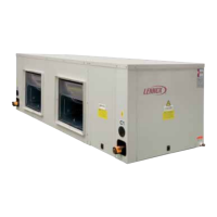
INDOOR
SECTION
OUTDOOR
SECTION
FOR UNIT MODELS: 48D2-64D2-76D2-86D2
2.- INSTALLATION
2.6.- ELECTRICAL CONNECTIONS
MULTI-SPLIT UNIT
24E/48D/
48D
2
32E/64D/
64D
2
38E/76D/
76D
2
86D/
86D
2
86D/
86D
2
MODELS VOLTAGE
230 V-3Ph-50Hz
230 V-3Ph-50Hz
400 V-3Ph-50Hz
230 V-3Ph-50Hz
400 V-3Ph-50Hz
LIMIT
180-242 V -3Ph- 50Hz
198-264 V -3Ph- 50Hz
342-462 V -3Ph- 50Hz
198-264 V -3Ph- 50Hz
342-462 V -3Ph- 50Hz
4
4
- BEFORE MAKING ANY ELECTRICAL CONNECTIONS, BE SURE THAT ALL CIRCUIT BREAKERS
ARE OPEN.
- IN ORDER TO CARRY OUT THE ELECTRICAL CONNECTIONS, FOLLOW THE ELECTRICAL DIAGRAM
SUPPLIED WITH THE UNIT.
Power supply.
Indoor motor fan electrical connection.
Electrical heater connection (optional).
Terminal-Thermostat connection
(See electrical connection for the controller).
2
2
3
3
1
PE L1 L2
X1
L3
3 ~ 230V - 50 Hz + PE
11
2
3
PE L1 L2 L3 N
X1
3N ~ 400V - 50 Hz + PE
11
2
3
 Loading...