Do you have a question about the Lennox BAC065DNM and is the answer not in the manual?
Specifies required equipment and procedures for safe lifting and positioning of the unit.
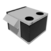
Provides physical measurements and weight specifications for different unit models.
Details methods for safely lifting various unit configurations using appropriate equipment.
Instructions for safely lifting and installing different types of roof curbs.
Guidance on installing the energy recovery module component.
Covers general site preparation, surface requirements, and critical clearances for unit placement.
Specifies required space around the unit for airflow, access, and maintenance.
Procedures for installing the unit on roof mounting frames, including types and assembly.
Instructions for correctly connecting the unit's electrical power supply and internal wiring.
Essential checks to perform before powering up the unit to ensure safe operation.
Procedures for safely initiating unit operation and verifying its initial function.
Detailed drawings and dimensions for various roof curb types used with the units.
Diagrams showing the setup and integration of energy recovery modules with the unit.
Procedures for maintaining fan belt tension and adjusting pulleys for proper operation.
Methods for adjusting system airflow and fan speed to meet performance specifications.
Guidance on filter replacement, cleaning, and monitoring for air quality and system efficiency.
Detailed instructions for installing, starting, troubleshooting, and maintaining gas burner heating systems.
Instructions for connecting external sensors, displays, and communication interfaces to the controller.
Procedures for integrating the controller with Building Management Systems (BMS).
Options for configuring unit inputs and outputs for custom control functions.
Procedures for programming unit operation schedules, time zones, and basic controller parameters.
Information on identifying, displaying, and resetting unit alarms and fault codes.
Schematic diagrams showing the refrigerant flow and key components within the system.
| Brand | Lennox |
|---|---|
| Model | BAC065DNM |
| Category | Air Conditioner |
| Language | English |