Page 21
NOTE – For horizontal applications in high humidity ar-
eas, remove the downow rail closest to the drain pan. To
remove rail, remove screw from rail at back of unit and at
cabinet support rail. Remove downow rail then replace
screws. Also, seal around the exiting drain pipe, liquid and
suction lines to prevent inltration of humid air.
10 - Knock out drain seal plate from access door. Secure
plate to cabinet front ange with screw provided.
11 - Flip access door and replace it on the unit.
12 - Set unit so that it is sloped 1/4ʺ toward the drain
pan end of the unit. Connect return and supply air
plenums as required using sheet metal screws.
13 - If suspending the unit, it must be supported along the
entire length of the cabinet. If using chain or strap,
use a piece of angle iron or sheet metal attached to
the unit (either above or below) so that the full length
of the cabinet is supported. Use securing screws no
longer than 1/2ʺ to avoid damage to coil or lter, as
illustrated in gure 13. Connect return and supply
air plenums as required using sheet metal screws.
RIGHT-HAND DISCHARGE
1 - Determine which plugs are required for drain line
connections.
2 - With access door removed, remove drain line plugs
to install drain lines.
3 - Set unit so that it is sloped toward the upow drain
pan end of the unit and level from front to back of
unit (see gure 7).
4 - The horizontal conguration is shown in gure 2.
Drains
AIR FLOW
PLUGS
RIGHT‐HAND DRAINS
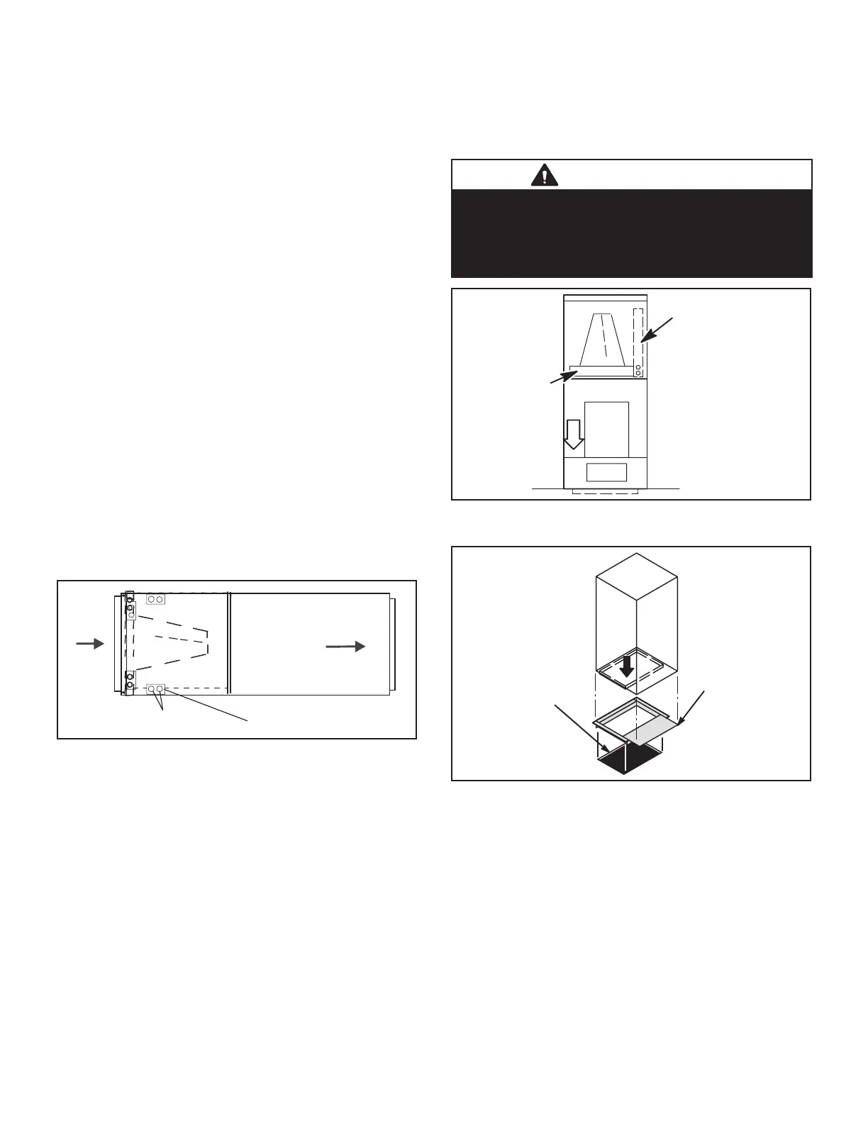
FIGURE 16. Right-Hand Discharge Conguration
5 - If the unit is suspended, the entire length of the
cabinet must be supported. If you use a chain or
strap, use a piece of angle iron or sheet metal
attached to the unit (either above or below) to
support the length of the cabinet. Use securing
screws no longer than 1/2 inch to avoid damaging
the coil or lter. See gure 13. Use sheet metal
screws to connect the return and supply air plenums
as required.
DOWNFLOW APPLICATION
NOTE – If downow application is required, separately or-
der kit number Y9658 (-018 through -030) or Y9659 (-036
through -060) and install per kit’s instructions. Also use
metal or class I supply and return air plenums.
Use the installation instruction provided with the downow kit.
IMPORTANT
If electric heat section with circuit breakers (ECBA25) is
installed in a CBA25UHV unit in a downow application,
the circuit breakers must be rotated 180° to the UP
position. See ECBA25 installation instructions for more
details.
HORIZONTA L DRAIN P
(REMOVE FROM UNIT)
UP-LOAD /
W
DRAIN PA N
FIGURE 17. Downow Discharge Position
Combustible Flooring Base
COMBUSTIBLE FLOOR
ADDITIVE BASE
PROPERLY SIZED
FLOOR OPENING
AIR
HANDER
UNIT
FIGURE 18. Downow Combustible Flooring Base
1 - For downow installation on combustible ooring,
an additive base must be used as illustrated in gure
18. See CBA25UHV Engineering Handbook for
downow combustible ooring base kits available
for this air handler.
2 - Cut an opening appropriately sized for combustible
base. Base dimensions are illustrated in gure 10.
After opening has been cut, set the additive base
into opening. Connect outlet air plenum to the
additive base. Set the unit on the additive base so
anges of the unit drop into the base opening and
seal against the insulation strips. The unit is now
locked in place. Install return air plenum and secure
with sheet metal screws.
 Loading...