19
MAIN AIR VENT: for down ow systems or dia-
phragm type expansion tanks (not provided)
Before a system is lled with water, there is air in
the pipes and radiation units. Some of the air will
be trapped as the system is lled. It is possible to
eliminate most of this air through the air vents on
the radiation units. A main air vent will speed and
simplify this process. The main air vent should be
installed on the highest point in the supply main
when all radiation is below the top of the boiler.
AUTOMATIC FILL VALVE (not provided)
For safe, efcient operation, a hot water system
must be lled with water. Adding new water, when
needed can be done manually (by use of a hand
valve in the water supply line). This requires regu-
lar attention to the system’s needs. An automatic
ll valve or pressure reducing valve accomplishes
this without attention. It is installed in the supply
line on hot water boilers only. The valve operates
through water pressure differentials. It does not
require an electrical connection.
BURNER SOLENOID VALVE (provided)
The Beckett and Carlin oil burner’s use a stan-
dard solenoid valve. Upon burner shut down, a
standard solenoid valve stops the ow of oil to the
nozzle. Without the solenoid valve, the oil pump
continues to pump oil to the burner nozzle until the
burner motor winds down below the pumps cutoff
speed. The Riello oil burner has a delay solenoid
valve. The delay solenoid valve provides the same
shut down action as the standard solenoid valve,
plus on burner start up the delay solenoid valve
remains closed for an additional 15 seconds.
This allows the burner fan motor to prepurge the
combustion chamber and the oil pump to bring
the supply oil pressure up to its set point helping
to provide a clean light off.
AQUASTAT RELAY CONTROL (provided)
The water temperature limit control in the aqua-
stat relay is adjustable and may be set: as low as
140°F so long as return water temperatures to
the boiler are no less than 120°F, or as high as
240°F so long as the boiler and heating system
have adequate circulation to remove the heat from
the boiler otherwise steam may be created in the
boiler. Refer back to SYSTEM PIPING section for
more information.
eQUipMeNT aNd OpTiONal aCCessOries
DRAIN VALVE (provided)
The drain valve is a manually operated valve that
provides a means of draining all the water from the
boiler and heating system. It should be installed in the
reducing tee where the return line enters the boiler.
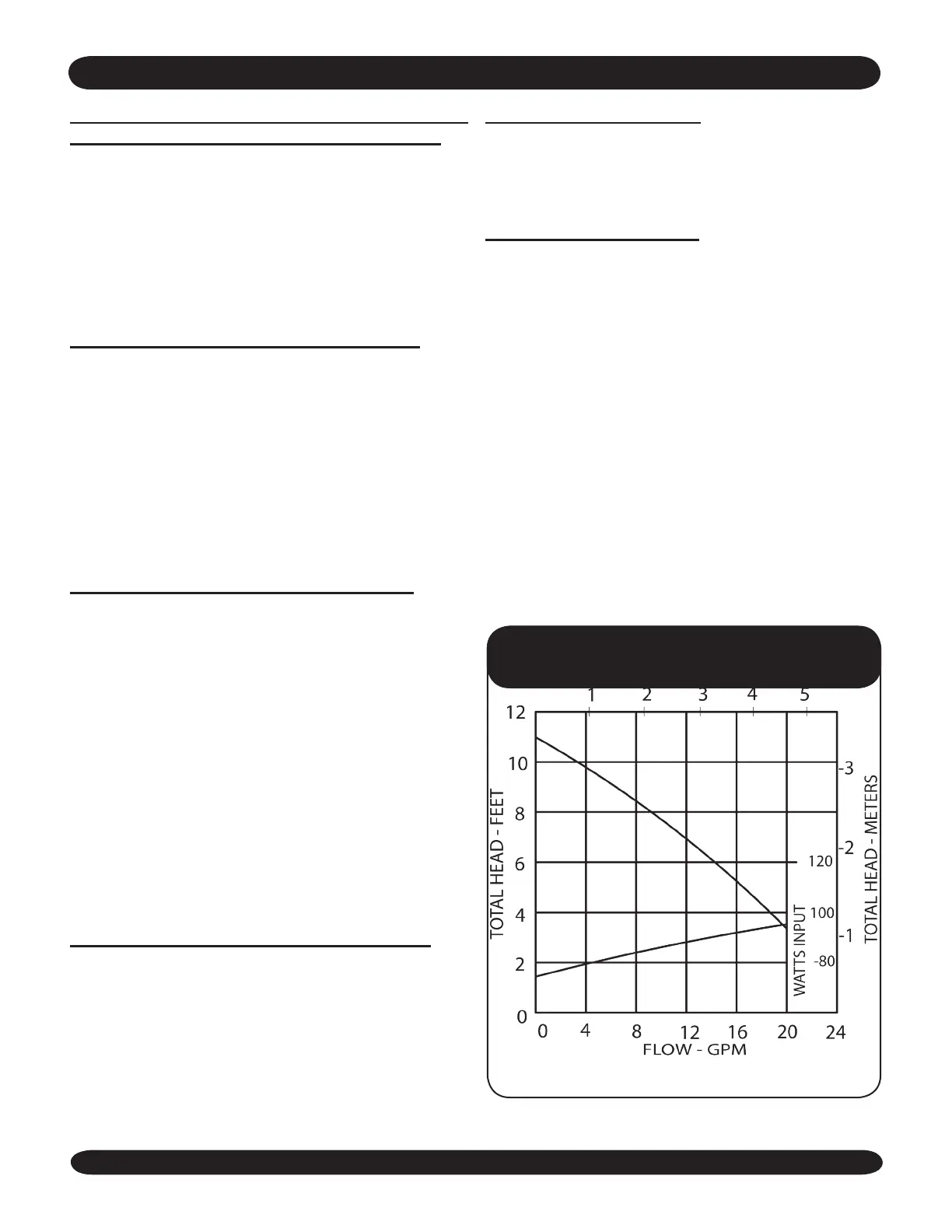
CIRCULATOR (provided)
Every forced hot water system requires a circulator. A
separate circulator or zone valve is required for each
zone, if there are two or more zones. The circulator
must have the capacity to provide the circulation
required by the heating system. The circulator
should be connected to the supply main and must
be wired into the boiler’s electrical system. See the
SYSTEM PIPING section for piping congurations
with the circulator located on the supply main piping
using zone circulators or zone valves. When the
piping is arranged with zone circulators and no
bypass piping, the circulator provided with the
boiler may be used as a zone circulator. Both piping
arrangements allow the circulator to pump away
from the expansion tank and show how the piping
should be arranged to allow the heating system to
be easily purged of air.
The pump curve for the furnished
Taco 007 pump is shown below
 Loading...