21
DO NOT TAMPER WITH THE UNIT OR CONTROLS
IMPORTANT You or your installer must follow these instructions carefully.
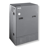
OperaTiNg THe BOiler
AIR SUPPLY FOR COMBUSTION: Do not install
the boiler in rooms with insufcient air, unless
corrective steps are taken. Occasionally, it is
necessary to install windows or cut holes in a door
to rooms used for supply air to obtain sufcient
combustion air and prevent less than atmospheric
air pressure in that room. If there is a lack of
combustion air, the burner ame will be dark
orange and the formation of soot will occur in the
heating unit. In buildings of conventional frame,
brick, or stone construction that do not have
utility rooms, basement windows, or stair doors,
air inltration is normally adequate to provide
enough air for combustion and for operation of
the barometric draft control. The room used for
supplying combustion air should be isolated from
any area served by exhaust fans. Refer back to
the section on FRESH AIR FOR COMBUSTION
for additional sizing guidelines.
DRAFT REGULATORS: A barometric draft
regulator is required for controlling the draft
through the boiler. The barometric draft regulator
is mounted in the chimney connector. Refer back
to the section on CHIMNEY AND CHIMNEY
CONNECTIONS. Once the draft regulator is
installed, use a draft gauge to adjust to the proper
opening: combustion chamber over re draft will
be approximately a 0.01” WC to 0.02” WC and
the stack draft will be approximately 0.02” WC. to
0.04” WC. On a larger installation, a greater draft
will be required in the stack to obtain the desired
over re draft.
STARTING: Fill the entire system with water. Vent
all air from the system following the section for
FILLING THE BOILER.
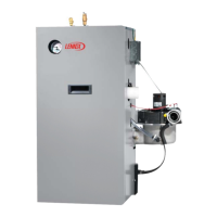
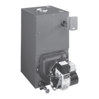
FUEL UNITS AND OIL LINES: Install oil
line(s) to the oil burner. Recommend using
heavy wall copper tubing and ared ttings, not
compression ttings. All connections and joints
must be absolutely airtight. Use an appropriate
nonhardening thread sealing compound on the
threaded connections, not Teon tape. See fuel
unit data sheet furnished with the burner for sizing,
lift, and length of tubing recommendations.
The original equipment oil burner (when
furnished) is equipped with a single stage fuel
unit with the bypass plug removed for single
pipe installation. This is satisfactory where the
fuel supply is on the same level as, or above the
burner, permitting gravity ow of oil. Per NFPA31
requirements, never exceed 3 psig pressure to
the inlet side of the fuel unit. When it is necessary
to lift the oil to the burner, a two pipe installation is
required. Run a return line between the fuel unit
and the oil supply. When a two pipe installation is
used, the bypass plug (furnished with the burner)
must be installed in the fuel unit. Refer to the
fuel unit instructions furnished with the burner
for specic instructions on installing the bypass
plug. Do not exceed the fuel unit manufacturer’s
recommendations for running vacuum.
NOTE: If lift exceeds 14 feet for Beckett or Carlin
burners or 11 feet for Riello burners, a twostage
fuel unit is required with a return line.
Install an oil lter of adequate size inside the
building between tank shutoff valve and the oil
burner. For ease of servicing, locate the shutoff
valve and lter near the oil burner.
 Loading...