9
1. When the installation of the boiler is for a new
heating system, rst install all of the radiation units
(panels, radiators, baseboard, or tubing) and the
supply and return mains. After all heating system
piping and components have been installed, make
nal connection of the system piping to the boiler.
It is recommended to mount the circulating pump
on the supply side piping, such that it pumps away
from the expansion tank. Refer to the gures on
the next pages.
2. A hot water boiler installed above radiation level
must be equipped with a low water cut off device.
A periodic inspection is necessary, as is ushing of
oat type devices, per low water cut off manufactur-
ers specic instructions.
3. The packaged boiler unit is set up with 1¼”
NPT supply and return piping from the front
of the boiler. The boiler supply and return piping
can be moved to the rear of the boiler. The boiler
should not be piped return line to the front, supply
line to the rear, or vice versa, as this will cause the
boiler water to short circuit the heat exchanger.
Piping connections may require additional ttings
and parts.
4. The relief valve is meant to be installed in the
back side of the rear section using the ¾” nipple
and street ell provided in the parts bag. Connect a
discharge pipe of the same pipe size (¾”) to carry
any water away to a drain. Do not connect directly
to a drain, but leave an air gap. No
shutoff of any description shall be
placed between the safety relief
valve and the boiler, or on discharge
pipes between such safety valves
and the atmosphere. Installation on
the safety relief valve shall conform
to the ANSI/ASME Boiler and Pres-
sure Vessel Code, Section IV. The
manufacturer is not responsible for
any water damage.
5. When connecting the cold water
supply to the pressure reducing
valve, make sure that a clean water
supply is available. When the water
supply is from a well or pump, a
sand strainer should be installed at
the pump.
sYsTeM pipiNg
!
!
Figure A
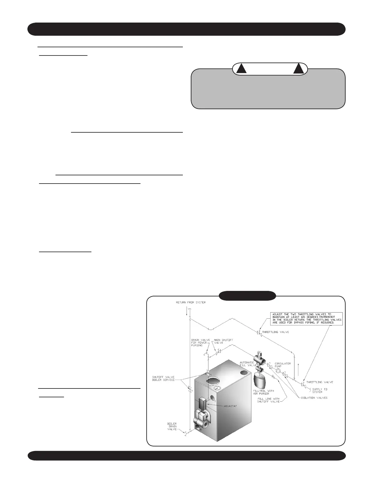
Low Design Water Temperature Systems (Be-
low 140° F) And Large Water Content Systems
WarNiNg
Signicant condensation may form in this boiler
and/or the venting system if the boiler is operat-
ed with return temperatures of less than 120° F.
This condensation is corrosive and can eventu-
ally cause severe damage to the boiler and vent-
ing system. The minimum design return water
temperature to prevent this condensation in the
boiler and venting is 120°F. The minimum high
limit setting is 140°F.
If the boiler is to be used in a heating system
where design water temperatures below 140°F
are desired (e.g. radiant oor heating), a 3way
or 4way mixing valve or suitable alternative
(e.g.bypass piping, Figure A) is required to pre-
vent low temperature (below return 120°F) re-
turn water from entering the boiler. When using
a mixing valve, follow the manufacturer’s instal-
lation instructions.
If the boiler is to be connected to a system hav-
ing a large water content (such as a former grav-
ity system), it is suggested to use bypass piping
shown in Figure A.
 Loading...