32
The three cables for connection from the keypad to the power
board must be kept separate from other cables, using an
individual cable channel; and use shielded cables, with a
cross-section of 1 mm
2
.
MODELS VOLTAGE LIMIT
009-011-015-019
009
019-021-025-029-035-
043-047-055-067-081
100-110-120-130
1N~230V-50Hz
3~230V-50Hz
3N~400V-50Hz
3~230V-50Hz
3N~400V-50Hz
1N~198-264V-50Hz
3~180-242V-50Hz
3N~342-462V-50Hz
3~198-264V-50Hz
3N~342-462V-50Hz
3N~400V-50Hz
3N~342-462V-50Hz
Three-lead shielded cable
with a cross-section of
1 mm
2
*
Terminal block
Remote
controller
(option)
2
1
x 1000
Electrical box
at the unit
PE L2L1
L3
PE NL
L2L1
L3
PE
N
230V THREE-PHASE
UNITS
400V THREE-
PHASE UNITS
230V SINGLE PHASE
UNITS
UNIT MODEL
POWER SUPPLY
0091S
0111S
0151S
0191S
0211S
0251S
0291S
0351S
0431S
0472S
0552S
0672S
0812S
NUMBER OF WIRES X SECTION
3 ~ 230V - 50 Hz + PE
3N ~ 400V - 50 Hz + PE
1N ~ 230V - 50 Hz + PE
1003S
1103S
1203S
1303S
---
---
---
---
---
---
---
---
---
---
---
---
---
---
---
---
---
---
---
---
---
---
---
---
---
---
---
---
---
---
---
---
---
---
---
---
---
---
---
---
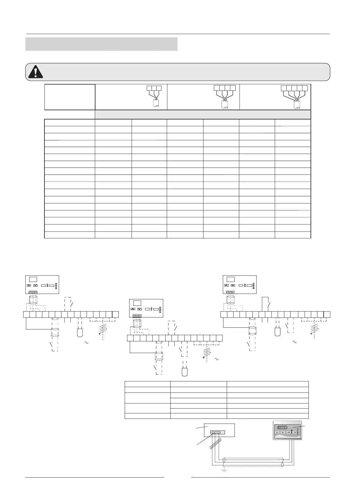
- AEH: Auxiliary Electric Heater
- The cable sections have been calculated based on a distance of 50m and variation of -10V.
Do not start the unit if the drop is greater than this.
- The wiring and circuit breakers to be mounted in the installation must comply with the Regulations in force.
- Ground wires must be properly connected and have a greater length than the phase wires.
A remote controller is offered as an option.
To install this option remote controller proceed as follow:
- Connect exactly as indicated in electrical diagram
- The wire should not exceed 50 m.
- BEFORE MAKING ANY ELECTRICAL CONNECTIONS, BE SURE THAT ALL CIRCUIT BREAKERS ARE OPEN AND SUPPLY IS OFF.
- IN ORDER TO CARRY OUT THE ELECTRICAL CONNECTIONS, FOLLOW THE ELECTRICAL DIAGRAM SUPPLIED WITH THE UNIT
(*) Remove wire.
(1) Remote changeover summer-winter
(Voltage free contact).
(2) Dynamic set point (outdoor sensor).
Not available for units EAC 0472 to 0812.
Without AEH With AEH Without AEH With AEH Without AEH With AEH
(**) For these models it is needed choose between (1) and (2) functions.
They can not operate simultaneously.
X1
(2)
PE 90 91 92 93 94 95 96 NL1
PE
R3
Alarm
L2 L397 98
Remote
ON / OFF
Screen wire
24 25 26
12
ON/OFF
RC
Option remote
keyboard
MODE
Screen wire
3N 400V 50Hz + PE
(*)
Screen wire
(1)
(2)
PE 90 91 92 93 94 95 96 NL1
PE X1
R3
Alarm
L2 L397 98
12
24 2526
ON/OFF
RC
Option remote
keyboard
MODE
Screen wire
Remote
ON / OFF
3N 400V 50Hz + PE
(EAR) 0091 TO 0431S
(**)
(*)
99 100
(1)
(2)
PE 90 91 92 93 94 95 96 NL1
PE X1
R3
Alarm
L2 L397 98
Remote
ON / OFF
Screen wire
12
24 25 26
ON/OFF
RC
Option remote
keyboard
MODE
Screen wire
3N 400V 50Hz + PE
(EAR) 0472 TO 1303S
(*)
2.6.- ELECTRICAL CONNECTIONS
VOLTAGE OPERATION LIMITS
2.- INSTALLATION
(EAC) 0091 TO 1303S
3 x 4 mm
2
3 x 10 mm
2
2
4 x 4 mm
2
4 x 4 mm
2
4 x 6 mm
2
4 x 10 mm
2
4 x 10 mm
2
4 x 10 mm
2
4 x 10 mm
2
4 x 16 mm
2
4 x 16 mm
2
4 x 25 mm
2
4 x 25 mm
2
4 x 35 mm
2
4 x 50 mm
2
4 x 6 mm
2
4 x 6 mm
2
4 x 10 mm
2
4 x 10 mm
2
4 x 10 mm
2
4 x 10 mm
2
4 x 16 mm
2
4 x 25 mm
2
4 x 25 mm
2
4 x 35 mm
2
4 x 35 mm
2
4 x 50 mm
2
4 x 50 mm
2
5 x 2,5 mm
2
5 x 2,5 mm
2
5 x 4 mm
2
5 x 4 mm
2
5 x 4 mm
2
5 x 4 mm
2
5 x 6 mm
2
5 x 10 mm
2
5 x 10 mm
2
5 x 10 mm
2
5 x 16 mm
2
5 x 16 mm
2
5 x 16 mm
2
5 x 4 mm
2
5 x 4 mm
2
5 x 4 mm
2
5 x 4 mm
2
5 x 4 mm
2
5 x 6 mm
2
5 x 10 mm
2
5 x 10 mm
2
5 x 10 mm
2
5 x 16 mm
2
5 x 16 mm
2
5 x 25 mm
2
5 x 25 mm
2
5 x 25 mm
2
5 x 35 mm
2
5 x 35 mm
2
5 x 80 mm
2
5 x 50 mm
2
5 x 50 mm
2
5 x 50 mm
2
5 x 70 mm
*Connection to be made by customer. MAXIMUM CABLE LENGTH 50m