• 68 • Installation - Operation - Maintenance manual • CHILLERS • ANNEXES - 0105-E
Pressure transducers HP & BP
04a 04b
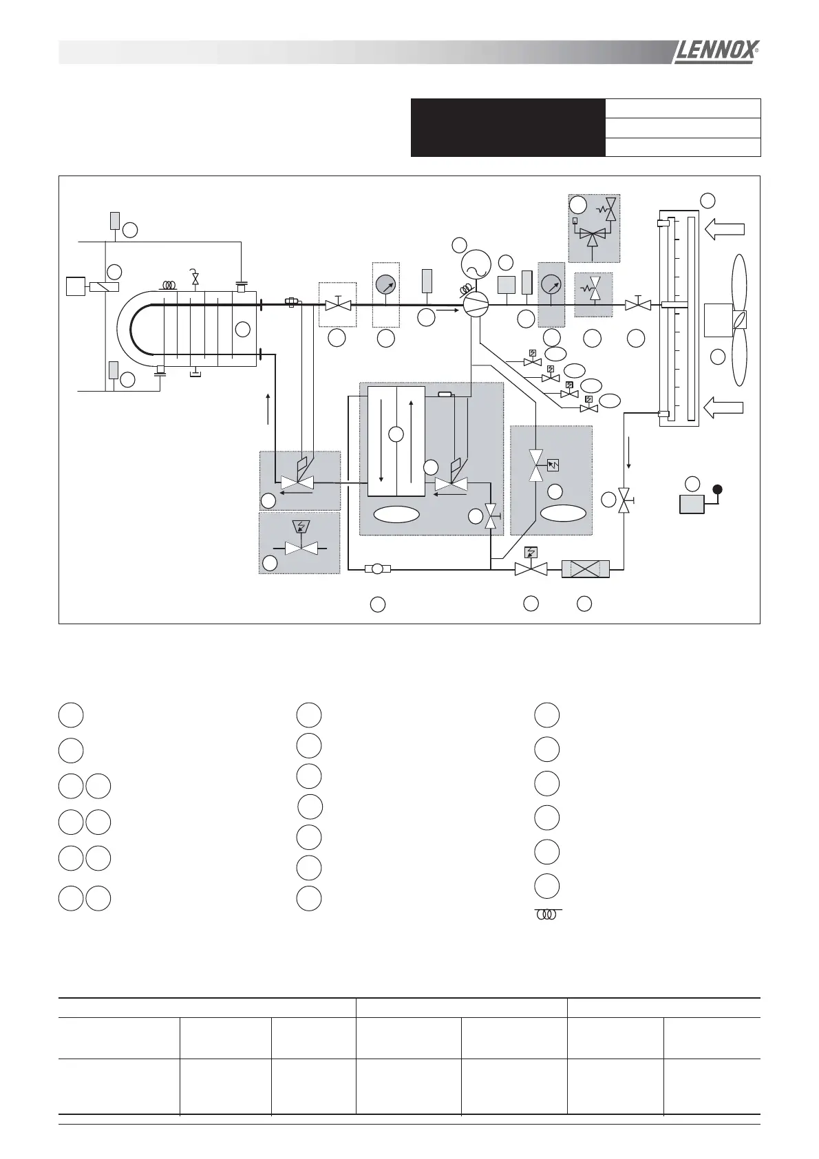
ECOMAX - REFRIGERANT DRAWING (SCREW COMPRESSOR)
standard
high ambient
low noise
all units
AIRFLOW
AIRFLOW
M
09
08
03
HP
P
04b
P
04a
06a
06b
19
Tex
CE
UDT
07a
07b
05b
P
05a
P
V
01
M
13
11
10
12
75%
50%
25%
ON
eco
14
10
17
15
14
17
16
D
T
T
20
18
18
12
HA
VARIANTS EXPANSION DEVICES OPTIONS
Basic Unit LCH with Eco LCH Unit Thermostatic Electronic HP LP Pressure Suction Isolating
CE or UDT Expansion valve Expansion valve Gauges valve
01 03 04a 04b 08 09 Add 07a Add Add Add Add
10 11 12 16 06a 13 17 14 10 or 07b 14 15 05a or 05b 06b
Refrigeration Circuit Component
Screw compressor
01
High pressure switch
03
Suction and discharge isolation
valves
06a 06b
Low and High pressure
manometer
05a 05b
Safety valve CE or UDT
07a 07b
Air cooled condenser
08
Fan motor
09
Manual isolating valve
10
Filter drier11
Solenoïd valve12
Sight glass
13
Electronic expansion valve
15
Shell and tube evaporator
16
Economiser heat exchanger
17
Temperature sensors
18
External temperature sensor
19
Water differential pressure switch
20
Thermostatic expansion valve
14
Heating resistance (option)
 Loading...