EasyManua.ls Logo

Lennox EL195UHE User Manual

Lennox EL195UHE
54 pages
To Next Page IconTo Next Page
Page #1 background imageLoading...
Page #1 background image
Page 1
© 2011 Lennox Industries Inc.
Litho U.S.A.
Corp. 1118−L4
Revised 11/2011
EL195UHE
Service Literature
EL195UHE SERIES UNITS
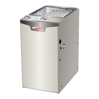
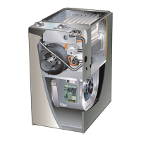
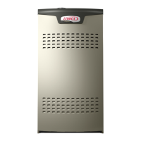
EL195UHE series units are high−efficiency gas fur-
naces manufactured with Lennox DuralokPlust alumi-
nized steel clamshell−type heat exchangers, with a stainless
steel condensing coil. EL195UHE units are available in
heating input capacities of 44,000 to 132,000 Btuh and
cooling applications from 2 through 5 tons. Refer to Engineer-
ing Handbook for proper sizing.
Units are factory equipped for use with natural gas. A kit is
available for conversion to LP/Propane operation. All
EL195UHE units are equipped with a hot surface ignition
system. The gas valve is redundant to assure safety
shut−off as required by C.S.A.
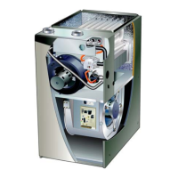
The heat exchanger, burners and manifold assembly can be
removed for inspection and service. The maintenance section
gives a detailed description on how this is done.
All specifications are subject to change. Procedures outlined
in this manual are presented as a recommendation only
and do not supersede or replace local or state codes.
WARNING
Electric shock hazard. Can cause injury
or death. Before attempting to perform
any service or maintenance, turn the
electrical power to unit OFF at discon-
nect switch(es). Unit may have multiple
power supplies.
Table of Contents
Specifications 2. . . . . . . . . . . . . . . . . . . . . . . . . . . . . . . . .
Optional Accessories 3. . . . . . . . . . . . . . . . . . . . . . . . . .
Blower Performance Data 4. . . . . . . . . . . . . . . . . . . . . .
I−Unit Components 7. . . . . . . . . . . . . . . . . . . . . . . . . . . .
II Placement and Installation 19. . . . . . . . . . . . . . . . . . . .
III−Start−Up 42. . . . . . . . . . . . . . . . . . . . . . . . . . . . . . . . . . .
IV−Heating System Service Checks 43. . . . . . . . . . . . . .
V−Typical Operating Conditions 46. . . . . . . . . . . . . . . . .
VI−Maintenance 47. . . . . . . . . . . . . . . . . . . . . . . . . . . . . . .
VII−Sequence of Operation and Flow Charts 50. . . . . .
WARNING
Improper installation, adjustment, alteration, service
or maintenance can cause property damage, person-
al injury or loss of life. Installation and service must
be performed by a licensed professional installer (or
equivalent), service agency or the gas supplier.
WARNING
Sharp edges.
Be careful when servicing unit to avoid sharp edges
which may result in personal injury.

Other manuals for Lennox EL195UHE

Question and Answer IconNeed help?

Do you have a question about the Lennox EL195UHE and is the answer not in the manual?

Lennox EL195UHE Specifications

General IconGeneral
ModelEL195UHE
TypeGas Furnace
Efficiency Rating95% AFUE
StagesTwo-stage
Blower TypeVariable-Speed
Fuel TypeNatural Gas or Propane
WarrantyLimited Lifetime Heat Exchanger, 10-year Parts

Summary

UNIT INFORMATION AND SAFETY

EL195UHE SERIES OVERVIEW

General introduction to the EL195UHE series gas furnaces, their features, and applications.

CRITICAL SAFETY WARNINGS

Essential safety precautions regarding electrical hazards, installation, and handling sharp edges.

UNIT SPECIFICATIONS

PERFORMANCE AND CONNECTION DATA

Details on heating performance, gas/drain connections, and blower specifications.

ELECTRICAL AND SHIPPING DATA

Electrical requirements and shipping weight information for the units.

ACCESSORIES AND KITS

CABINET, DRAIN, AND FILTER KITS

Optional accessories for cabinet mounting, condensate drainage, and air filtration.

VENTILATION AND GAS HEAT ACCESSORIES

Termination kits for venting and accessories for gas heating systems.

BLOWER PERFORMANCE DATA (MODELS 045-090)

EL195UH045XE36B PERFORMANCE

Air volume and wattage performance data for the 045 model.

EL195UH070XE36B PERFORMANCE

Air volume and wattage performance data for the 070 model.

EL195UH090XE48C PERFORMANCE

Air volume and wattage performance data for the 090 model.

BLOWER PERFORMANCE DATA (MODELS 110-135)

EL195UH110XE60C PERFORMANCE

Air volume and wattage performance data for the 110 model.

EL195UH135XE60D PERFORMANCE

Air volume and wattage performance data for the 135 model.

PARTS IDENTIFICATION

MAJOR COMPONENT LOCATIONS

Diagram illustrating the location of key furnace components.

I-UNIT COMPONENTS

ESD PRECAUTIONS AND CONTROL BOX COMPONENTS

Guidelines for handling static-sensitive components and identifying parts within the control box.

KEY CONTROL BOX COMPONENTS

Details on transformer, interlock switch, circuit breaker, and ignition control.

WIRING TERMINALS AND DIAGNOSTIC CODES

QUICK CONNECT TERMINAL IDENTIFICATION (TABLE 3)

Reference for identifying various quick connect terminals on the control board.

FURNACE DIAGNOSTIC CODES (TABLE 4)

List of LED flash codes indicating furnace status and error conditions.

INTEGRATED CONTROL SYSTEM OPERATION

ELECTRONIC IGNITION AND SAFETY SEQUENCES

Explanation of the ignition process, safety interlocks, and control board functions.

FAN OPERATION AND DELAY SETTINGS

Information on how to adjust fan on/off delays for heating and cooling.

HEATING COMPONENTS OVERVIEW

COMBUSTION AIR SYSTEM COMPONENTS

Description of the combustion air inducer, flame rollout switches, heat exchanger, and primary limit control.

KEY HEATING COMPONENTS DETAILS

GAS VALVE, FLAME SENSOR, AND IGNITOR FUNCTION

Detailed explanations of the gas valve, flame sensor, and ignitor operation and testing.

FLAME SIGNAL MEASUREMENT

FLAME SIGNAL SPECIFICATIONS AND MEASUREMENT DIAGRAM

Data on flame signal values and instructions for measuring it.

IGNITOR TESTING PROCEDURES

RESISTANCE AND VOLTAGE TESTS FOR IGNITOR

Step-by-step guide for testing the ignitor's electrical properties.

COMBUSTION AIR SYSTEM COMPONENTS

COMBUSTION AIR INDUCER AND PRESSURE SWITCH

Explanation of the inducer, header box, and the function/troubleshooting of the pressure switch.

PRESSURE DIFFERENTIAL MEASUREMENT

PROCEDURE FOR MEASURING PRESSURE DIFFERENTIAL

Detailed instructions and diagram for measuring pressure differential using a manometer.

PRESSURE SWITCH TROUBLESHOOTING AND IGNITION SEQUENCE

PRESSURE SWITCH TROUBLESHOOTING GUIDE

Table and guidance for diagnosing issues related to the pressure switch.

HEATING SEQUENCE OF OPERATION FLOWCHART

Visual representation of the furnace's heating cycle and fault detection.

BLOWER COMPARTMENT COMPONENTS

BLOWER WHEEL/MOTOR REPLACEMENT AND SECONDARY LIMITS

Instructions for blower replacement and explanation of secondary limit controls.

BLOWER MOTOR WIRING VERIFICATION

120V AND 24V POWER SUPPLY TESTS

Procedures for testing voltage supplies to the blower motor and its speed taps.

INSTALLATION: PIPE AND FITTING SPECIFICATIONS

PIPE, FITTINGS, PRIMER, AND CEMENT REQUIREMENTS

Specifications for approved piping materials, primers, and cements.

VENT TERMINATION KITS AND PIPE JOINING

OUTDOOR TERMINATION KITS USAGE (TABLE 9)

Guide to selecting appropriate termination kits for various vent pipe sizes and models.

JOINT CEMENTING PROCEDURE AND SAFETY WARNING

Instructions for cementing pipe joints, including safety precautions for flammable fumes.

VENTING PRACTICES AND PIPING GUIDELINES

PIPING SUPPORT, WALL THICKNESS, AND EXHAUST TERMINATION

Guidelines for pipe suspension, wall thickness, and safe exhaust pipe termination.

VENT PIPING SIZING AND MINIMUM LENGTHS

VENT PIPING SIZING FLOWCHART AND MINIMUM LENGTHS (TABLE 10)

Guidance on determining correct vent pipe size and minimum required lengths.

MAXIMUM VENT PIPE LENGTHS (STANDARD TERMINATION)

ALLOWABLE INTAKE/EXHAUST VENT LENGTHS (TABLE 11)

Table detailing maximum vent pipe lengths for standard terminations at different elevations.

MAXIMUM VENT PIPE LENGTHS (CONCENTRIC TERMINATION)

ALLOWABLE INTAKE/EXHAUST VENT LENGTHS (TABLE 11)

Table detailing maximum vent pipe lengths for concentric terminations at different elevations.

MAXIMUM VENT PIPE LENGTHS (SPECIAL INSTALLATIONS)

VENT LENGTHS FOR CLOSET/BASEMENT INSTALLATIONS (TABLE 12)

Table specifying maximum vent lengths for installations in confined spaces.

TYPICAL EXHAUST AND INTAKE PIPE CONNECTIONS

UPFLOW VENT APPLICATION CONNECTIONS

Diagrams illustrating vent pipe connections for upflow installations.

HORIZONTAL VENT APPLICATION CONNECTIONS

Diagrams illustrating vent pipe connections for horizontal installations.

INTAKE PIPING INSTALLATION GUIDELINES

UPFLOW AND HORIZONTAL INTAKE PIPE SETUP

Instructions and diagrams for installing intake piping in various configurations.

VENT TERMINATION AND CONFINED SPACE GUIDELINES

CONFINED SPACE INSTALLATION CAUTIONS AND VENT TERMINATION GUIDELINES

Safety warnings for confined spaces and general rules for vent termination placement.

MAXIMUM UNINSULATED EXHAUST VENT LENGTHS

UNINSULATED VENT LENGTHS BASED ON WINTER TEMPERATURES (TABLE 13)

Table specifying maximum uninsulated vent pipe lengths according to ambient temperature.

VENT TERMINATION CLEARANCES (NON-DIRECT VENT)

USA AND CANADA CLEARANCE REQUIREMENTS FOR NON-DIRECT VENTS

Diagram and table detailing clearance requirements for non-direct vent terminations.

VENT TERMINATION CLEARANCES (DIRECT VENT)

USA AND CANADA CLEARANCE REQUIREMENTS FOR DIRECT VENTS

Diagram and table detailing clearance requirements for direct vent terminations.

DIRECT VENT EXHAUST PIPING TERMINATIONS

EXHAUST PIPING ROUTING AND TERMINATION GUIDELINES

Instructions on routing and terminating exhaust pipes in direct vent systems.

EXHAUST PIPE TERMINATION SIZE REDUCTION (TABLE 14)

Table specifying reducer sizes for exhaust pipe terminations.

VENT TERMINATION CLEARANCE DIAGRAMS

FIGURE 32 - VENT TERMINATION CLEARANCE DETAILS

Illustration showing specific measurements for vent termination clearances.

FIELD-SUPPLIED WALL TERMINATION KITS

WALL RING TERMINATION KIT INSTALLATION DIAGRAMS (FIGURE 33 & 34)

Diagrams illustrating the installation of wall termination kits.

TYPICAL TERMINATION KITS AND CONFIGURATIONS

VARIOUS DIRECT VENT TERMINATION KIT DIAGRAMS

Illustrations of different termination kits for side wall, rooftop, and concentric applications.

EXTENDED VENT KITS FOR GRADE CLEARANCE

USA CLOSE-COUPLE EXTENDED VENT INSTALLATION (FIGURE 41)

Diagram showing the installation of US close-couple extended vent kits.

CANADIAN CLOSE-COUPLE EXTENDED VENT INSTALLATION (FIGURE 42)

Diagram showing the installation of Canadian close-couple extended vent kits.

DIRECT VENT APPLICATION WITH EXISTING CHIMNEY

CHIMNEY TERMINATION INSTALLATION DIAGRAM (FIGURE 43)

Illustration for direct vent installations using an existing chimney.

NON-DIRECT VENT EXHAUST PIPING TERMINATIONS

Guidance on routing and terminating exhaust piping for non-direct vent systems.

NON-DIRECT VENT APPLICATION WITH EXISTING CHIMNEY AND CONDENSATE PIPING

CHIMNEY TERMINATION INSTALLATION DIAGRAM (FIGURE 47)

Illustration for non-direct vent installations utilizing an existing chimney.

CONDENSATE PIPING INSTALLATION PROCEDURES

Instructions for installing condensate traps and drain lines, including safety warnings.

CONDENSATE DRAINAGE CONFIGURATIONS

SEPARATE DRAINAGE FOR FURNACE AND EVAPORATOR COIL

Diagrams illustrating separate condensate drain setups for upflow and horizontal units.

COMBINED CONDENSATE DRAINAGE SYSTEMS

COMMON DRAINAGE FOR FURNACE AND EVAPORATOR COIL

Diagrams detailing common drain configurations, including venting requirements.

CONDENSATE TRAP AND DRAIN ASSEMBLY DETAILS

PVC DRAIN ASSEMBLY CONFIGURATIONS (FIGURE 55)

Illustrations showing various methods for assembling condensate traps and drains using PVC piping.

III-START-UP PROCEDURES

PRELIMINARY CHECKS, HEATING START-UP, AND GAS VALVE OPERATION

Step-by-step instructions for starting the furnace, including safety checks and gas valve operation.

FAILURE TO OPERATE TROUBLESHOOTING CHECKLIST

A guide to diagnose and resolve common operational issues.

IV-HEATING SYSTEM SERVICE CHECKS

GAS PIPING INSTALLATION, TESTING, AND PRESSURE MEASUREMENT

Procedures for gas piping, leak detection, and pressure testing, including supply and manifold pressures.

COMBUSTION EFFICIENCY AND HIGH ALTITUDE CONSIDERATIONS

PROPER COMBUSTION CHECKS AND HIGH ALTITUDE REQUIREMENTS

Guidance on checking combustion efficiency and requirements for high-altitude installations.

ELECTRICAL GROUNDING AND VOLTAGE VERIFICATION

GROUNDING AND VOLTAGE CHECKS FOR INTEGRATED CONTROL

Procedures for verifying proper grounding and voltage levels supplied to the control system.

V-TYPICAL OPERATING CHARACTERISTICS

BLOWER OPERATION, TEMPERATURE RISE, AND STATIC PRESSURE

Explanations of blower function, temperature rise calculations, and static pressure measurement.

BLOWER SPEED TAP ADJUSTMENT PROCEDURES

Instructions for changing blower speed settings via the integrated control.

VI-MAINTENANCE PROCEDURES

ROUTINE CHECKS: BLOWER, FILTERS, PIPING, AND ELECTRICAL

Maintenance tasks including blower cleaning, filter inspection, pipe checks, and electrical system verification.

WINTERIZING, CONDENSATE TRAP CARE, AND HEAT EXCHANGER CLEANING

Procedures for seasonal maintenance, including unit winterizing, trap cleaning, and heat exchanger cleaning.

VI-MAINTENANCE: BURNER ASSEMBLY CLEANING

BURNER ASSEMBLY CLEANING PROCEDURES

Detailed steps for removing, cleaning, and inspecting the furnace burner assembly.

VI-MAINTENANCE: BURNER ASSEMBLY REASSEMBLY

REASSEMBLY AND FINAL CHECKS AFTER BURNER CLEANING

Instructions for reassembling the burner assembly and ensuring proper furnace operation.

VII-WIRING DIAGRAM AND HEATING SEQUENCE OF OPERATION

WIRING DIAGRAM OVERVIEW AND COMPONENT CONNECTIONS

Explanation of the furnace's wiring diagram and the function of various connections.

HEATING SEQUENCE OF OPERATION DESCRIPTION

Step-by-step explanation of how the furnace operates during a heating cycle.

TROUBLESHOOTING HEATING SEQUENCE (PART 1)

NORMAL VS. ABNORMAL HEATING MODES AND LED CODES

Flowchart detailing the heating sequence and common faults indicated by LED flash codes.

TROUBLESHOOTING HEATING SEQUENCE (PART 2)

DETAILED HEATING SEQUENCE CHECKLIST AND FAULT RESOLUTION

Continuation of the heating sequence troubleshooting, covering more fault conditions and response actions.

TROUBLESHOOTING COOLING SEQUENCE OF OPERATION

NORMAL VS. ABNORMAL COOLING MODES AND LED CODES

Flowchart outlining the cooling cycle, potential issues, and corresponding LED error codes.

TROUBLESHOOTING CONTINUOUS FAN AND ACCESSORY SEQUENCES

FAN AND ACCESSORY OPERATION FLOWCHARTS

Flowcharts illustrating the operation of continuous fan mode and accessory functions.

Related product manuals